Alignments, points, polylines and other entities supported by CGS Labs solutions can be now projected/draped to surfaces that are stored in external DWG files. Thus, preserving the design drawing a small amount of data and thus better manageability, faster drawing manipulation, and producing small final drawings with all design elements needed: the profile, cross-sections, polylines projected to surfaces (3d polylines) and more.
All types of surfaces are supported:
- CGS Labs surfaces,
- AutoCAD Civil 3D surfaces,
- BricsCAD surfaces as well as
- native 3D Faces.
CGS Labs surfaces are supported on all CAD platforms. The only functional limitation present AutoCAD and BricsCAD platforms and their surface types, where within Autodesk products you can drape Plateia objects to Autodesk surfaces located in external files. Same for BricsCAD. In short, trying to project Plateia alignment when working on the AutoCAD Civil 3D platform will not support projection to a surface made with BricsCAD which is stored in the external reference file.
This tutorial consists of two parts. In the first part, the use of terrain in external DWG files will be shown in the example of alignment design with the Plateia software. The same procedure also applies to the Ferrovia and Aquaterra. A similar process is also used in the Autosign software, except that you run a different command for projection. Click here to read more about external surfaces in Autosign.
The second part of the tutorial shows an example of how to project a 2D/3D polyline to the surface in an external DWG file. Tools from Site Design will be used for this.
1. Download the material
First, download the Tutorial_ExternalSurfaces.zip file that is attached to this document.
This zip file contains the following drawings:
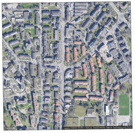
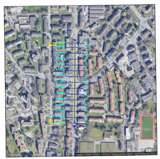
- Project: the drawing with the raster, which will help us draw the alignment and 3D polyline.
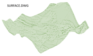
- Surface_01: the drawing with two CGS Labs terrains.
- Suface_02: the drawing with 3D faces.
- Raster: raster image from Google Maps.
Project drawing:
Surface_01 drawing:
2. Project an alignment to surface
2.1 Define a new alignment
1. Open the Project drawing.
2. Run the Alignment Manager command.

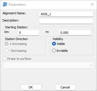
3. Define the Alignment Name and click the OK button.
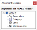
After that, a new dialogue box named Alignment Manager opens. This is intended for the management of alignments present in the drawing. In this dialogue box, you can then edit axis parameters, category and station. You can also add new or delete the existing axis directly in this dialogue with the right-click anywhere in the window.
4. In the Alignment Manager dialogue box double-click on the Category.

5. In the Standard dialogue box define the following parameters:
- road function: Approach roads,
- road type: Local road -LC,
- terrain type: Flat and
- design speed: 50 km/h.
You can also preview Critical parameters and a Standard overview at the bottom of the dialogue box.

6. Confirm by pressing OK.
You can then double-click on the Lanes option and change widths or leave it as is.
2.2 Design alignment
IMPORTANT! Before you start drawing an alignment you have to always check that this axis is set as active (the icon next to the alignment name is coloured blue). If it is not, double-click on the axis in the Alignment Manager.
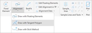
1. Run the Draw with Tangent Polygon command.
2. In Create Tangent Polygon dialogue box, check at Automatic, Draw Spirals and Draw with Tangent Polygon boxes.
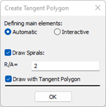
3. Confirm by clicking the OK button.
4. Select the first point of the tangent polygon in the drawing. Continue with inserting a tangent polygon interactively. The main elements are drawn across. When finished, press Enter.
5. It opens the Draw lanes and widenings dialogue box. In this dialogue box, you can uncheck the box at the Draw Widenings.
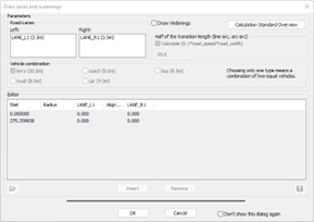
You can also select the vehicle combination. Based on the parameters in this dialogue box, widenings will be calculated. You can also change the widenings manually by clicking in the Editor part of the dialogue box.
6. After you check all the parameters you can confirm by clicking OK. The tangent polygon is then drawn in the drawing as shown on the right:

2.3. Drape
Now you need to project the alignment to the surface.
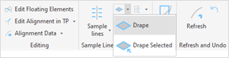
1. Run the Drape command.
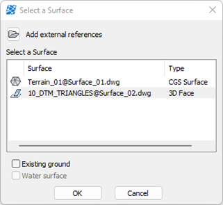
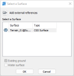
It opens the Select a Surface dialogue box.
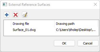
2. Click on the Folder icon at the top of the dialogue box.

In this dialogue box, now define where the surfaces are located.
3. Click on the Plus button and find the Surface_01 drawing.


Later, you can also remove drawing files or change the path. (You can also add several surface drawings at once.)
NOTE! The drawing with the surface that you want to drape to must not be open.
4. Click OK.
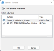
All surfaces from the drawing are displayed in the Select a surface dialogue box. Surfaces also get a suffix, which represents the name of the drawing.
5. Click on the Terrain_01@Surface_01 and click the OK button.
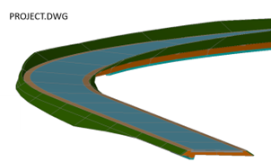
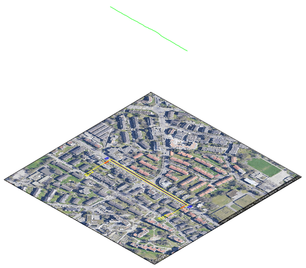
The alignment is now draped on the selected surface:
2.4. Drape on another terrain
If necessary, you can also project to additional terrains that are also not in the drawing in which you design the alignment.
1. Click on the Drape icon.

It opens the Select a Surface dialogue box.
2. Click on the Folder icon at the top of the dialogue box.
In this dialogue box, now define where the surfaces are located.
3. Click on the Plus button and find the Surface_02 drawing.
Later, you can also remove any surfaces or change the path. (You can also add several surface drawings at once.)
NOTE! The drawing with the surface that you want to drape to must not be open.
4. Click OK.
In the Surface_02 drawing, we only have 3D faces, therefore, the name of the surface is now defined a little differently.
The first part of the name represents the name of the layer, on which 3D faces are. The second part of the name is generated as in the previous example and represents the name of the drawing.
5. Click on the 10_DTM_TRIANGLES@Surface_02.dwg and click on the OK button.


![]()
You can then continue with drawing profile and cross-sections according to the classical Plateia procedure. You can also add sample lines at any time, which will be automatically projected to the terrain.
3. Project 2D/3D polyline to surface in Site Design
1. Draw an arbitrary 3D polyline within the raster image area. Use the CAD command (3DPOLY) for this.
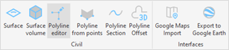
2. Run the Polyline Editor command.
3. Click on the previously drawn 3D polyline and its name will appear in the 3D Polyline editor dialogue box.
4. Then right-click on the name of the 3D polyline and select the Raise to surface elevation (add vertex on surface break) option.

5. Select a surface to drape the 3D polyline to. If you want to drape onto a surface that is not listed in this dialogue box, click on the folder icon and define a drawing.
6. Click on the Terrain_01@Surface_01.dwg and click OK.
3D polyline result with surface heights applied to 3D polyline vertices where the surface is stored in an external reference file:

If you are interested in CGS Labs software and would like to get further information or download a free trial.
