Railway infrastructure is a complex and multi-disciplinary engineering system that must be planned very carefully and consistently. In general, the characteristic cross-section covers the steel rails that are installed on sleepers, set in ballast. In addition, there are also many drainage elements along the railway line, as well as signal safety and telecommunication devices. Due to the design and technical elements, the railway often passes through many bridges, tunnels, portals and other demanding structures. Because of all these facilities, railway projects are very difficult, therefore it is necessary to use BIM in designing, planning, building and maintenance.

Characteristic cross-section, created with the Ferrovia software.
CGS Labs solutions provide extensive BIM data support not limited to CAD platforms in use. Ferrovia enables to easily generate detailed 3D solid objects along the rail alignment. Those solids can be also automatically attached by metadata, defined in BIM Execution Plan. For the user to create a model quickly and as easily as possible, all BIM-related commands are collected in the Utility tab.

The Utility tab in the Ferrovia software.
The first command in the Utility tab is Draw 3D model. Ferrovia creates a model by connecting planimetry quantities from the cross-sections between individual sample lines. This is the reason that the sample lines should be drawn more densely, especially in the area of the curve, if you want a more accurate model.
Then the user has three different commands for working with metadata. Even before drawing a BIM model, the Property Manager is used for defining property sets and associated attributes. Then we run the Draw 3D model command, where we define which quantities should be drawn as 3D solids and which property sets should be automatically attached to individual quantities.
3D model of the railway and concrete bridge.
Once we have a BIM model created, we can view the metadata using the Property Set Editor. With the help of this functionality, the user can also add property sets to elements in the drawing that were not created using the Draw 3D model command. There is also a Property Set Filter in the Utility tab, which allows you to quickly search for 3D solid objects, based on their attributes.
The user also has a function to detect collisions between individual elements and commands for IFC import and export. The latter is very important for participation in more complex projects, where designers make their part of the project in different software. The previous figure shows a bridge imported from an IFC file.
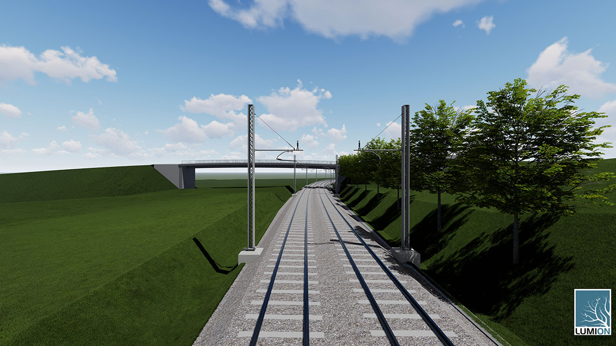
Last month, we set out a demo project to test the capabilities of the Ferrovia software. We created a BIM model of a double-track railway line that runs under a concrete bridge. The model also includes a noise barrier, masts and signal safety devices. The results will help us for further development, where we will also place great emphasis on supporting IFC Rail.

The visualization of railway, noise barrier and concrete bridge.
If you are interested in Ferrovia and would like to get further information or download a free trial.
