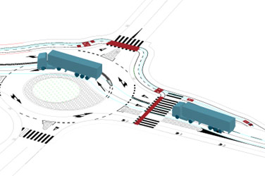
Autopath, vehicle swept path analysis and turn simulation

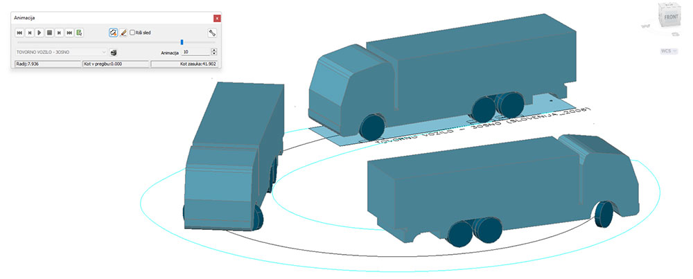
Vehicle swept path analysis & 3D animation
Autopath is a professional software solution for vehicle swept path analysis used by civil engineers, transportation professionals, architects, and urban planners. Autopath enables the simulation and analysis of vehicle manoeuvres, 3D vehicle animation and more.

Intuitive user interface
Autopath is distinguished by its carefully designed UI and workflow that make it fast to learn and easy to use. Competitive pricing, service for designing complex custom vehicles, and high-level technical support make Autopath the product of choice for professionals worldwide.
Our Customers’ Journey


Vehicle libraries
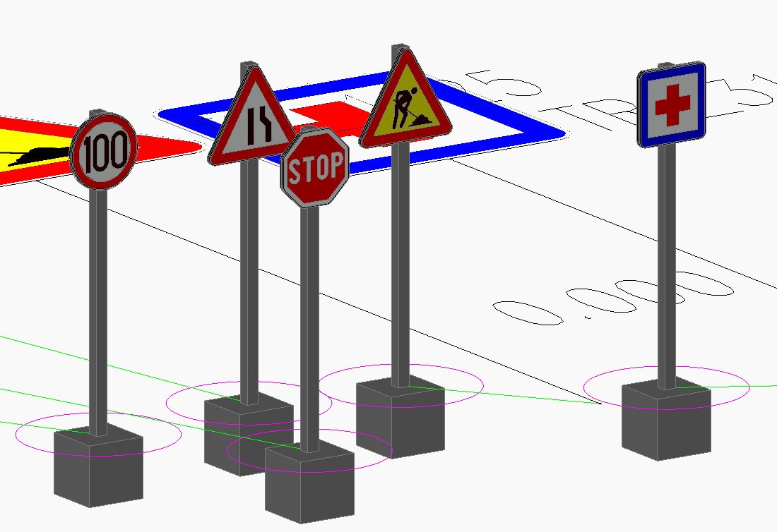
![]() AUTOPATH includes several country-specific reference vehicle libraries defined by national guidelines, and an extended collection of vehicles from different manufacturers, covering aircraft, buses, cranes, emergency vehicles, trucks, agricultural machinery and more.
AUTOPATH includes several country-specific reference vehicle libraries defined by national guidelines, and an extended collection of vehicles from different manufacturers, covering aircraft, buses, cranes, emergency vehicles, trucks, agricultural machinery and more.
| USA / CANADA / INDIA | AASHTO 2014 (Imperial / Metric), AASHTO 2011 (Imperial / Metric) |
| CANADA | TAC 2017 |
| EUROPE | United Kingdom (FTA 2016, FTA 1998) |
| Irish national vehicle library | |
| Germany (Deurschland 2005), Deutschland RBSV_2020 | |
| Austria (Österreich) | |
| Sweden (Sverige 2005) | |
| Norwegian (Norge 2007) | |
| Poland (Polska 2016) | |
| Hungary (Magyarország 2005) | |
| Czech Republic (TP 171, 2005) | |
| Croatia (Hrvatska 2001) | |
| Serbia (Serbia 2012) | |
| Slovenia (Slovenija 2006) | |
| Romania (Romania 1985) | |
| North Macedonia | |
| Turkey (Türkiye) | |
| RUSSIA | POCCŃЯ |
| AUSTRALIA | Australia 1993, Australia 2013, Australia 2018 |
| NEW ZEALAND | New Zealand 2007 Auckland Transport 2022 Auckland Transport 2016 |
| AFRICA | South Africa (South Africa 1988), Tanzanai (TANZANIA_2011) |
| UAE | UAE (United Arab Emirates 2017) |
| ISRAEL | Israel (Israel 2011) |
In the latest version, Autopath gets an extensive number of vehicle libraries and utility vehicle types added to the existing vehicle list, vehicle types ranging from agricultural vehicles, emergency vehicles, buses, trucks, trailers for wind turbine transport, cranes, forklifts and more.
| BUS | Ikarus, Kravtex, Man, Mercedes, Neoplan, Rába, Setra, Volvo |
| CRANE KATO | CR-100, CR-250, MR-130, NK-300E-v, NK550vr ► we support vehicles with all wheels steering |
| CRANE LIEBHERR | LTM1030-2.1, LTM1040-2.1, LTM1050-3.1, LTM1055-3.2, LTM1060-3.1, LTM1070-4.2, LTM1090-4.1, LTM1100-5.1, LTM1100-5.2, LTM1350-6.1, LMT1250-5.1 ► we support vehicles with all wheels steering |
| CRANE TEREX | AC55-3 (385/95R25) AWS(3), AC55-3 (445/95R25) AWS (3), AC60-3 (385/95R25) AWS(3), AC60-3 (445/95R25) AWS (3), AC140 (385/95R25) ASW (3), AC140 (445/95R25) AWS(3), AC160-2 (385/95R25), AC160-2 (445/95R25), AC160-5 (385/95R25) AWS (3), AC160-5 (445/95R25) AWS (3), AC160-5 (525/80R25) AWS (3), AC250-1 (525/80R25), TEREX MAX 25 ► we support vehicles with all wheels steering |
| CUSTOM | Wind Transport, Heavy Load Vehicle, Long Cargo Vehicle |
| EMERGENCY EUROPE | Mercedes Benz, Tatra, Man, Iveco |
| EMERGENCY AASHTO | Fire Vehicle – Pumper, Fire Vehicle – Aerial Platform |
| GOLDHOFER | Drop-Deck Semitrailler, Europe Flatbad, Flatbad with Pendular Axles |
| MINING TRUCKS CAT | 785D, 770G, 797F, 772G, 773G, 775G, 777G, 789D, 793D, 793F, 794AC, 796AC, 798AC |
| MINING TRUCKS KOMATSU | HD325-7R, HD465, HD465, 730E, 830E-AC, 860E-1K, 930E-4, 930E-4SE, 960E-1, HD1500-7, HM300-2R (ARTICULATED), HM400-3R (ARTICULATED) |
| EMERGENCY SLO | PV-1, PV-2, GV-1, GVV-1, GVV-2, GVC-16/15, GVC-16/25, GV-16/24, GVC-24/50, AC, GVGP-1, GVGP-2 |
| TRUCK | Mercedes Benz, Iveco, MAN |
| WHEEL LOADER | Sonnebogen 355 E, LIEBHER_L544, LIEBHER_L506compact, LIEBHER_L585, MLT 741-140 V+, MLT 961-160 V+L, MLT 741-130 PS+, STEYR_6125, STEYR_6125 + CMC-ST-300, VOLVO (L110H, L120H, L50H) |
| CONCRETE MIXER | MAN TGS 41.420 8×4; ITAS CAS |
| AGRICULTURAL MACHINERY | Tractor John Deere 5603 4WD, Tractor Fendt 936 Vario, Tractor + Bailey Dumper DUMP10, Tractor + Bailey Grain Trailer TAG11, Tractor + Bailey Baby Trailer BR2.0, Tractor + Bailey Low Loader LOW 8/16 |
| AMBULANCE EUROPE | TYPE A, TYPE A2, TYPE B, TYPE B1, TYPE C |
| BICYCLE | Normalrad, Muli Pendix, Douz G4 Traveller, Christiana |
| BULKCEMENT TRAILER | PREPRAVNIKY NCJ 32, PREPRAVNIKY NCJ 36, PREPRAVNIKY NCJ 40, PREPRAVNIKY NCJ 45, PREPRAVNIKY NCJ 46, PREPRAVNIKY NCJ 54, SKLOPNE PREPRAVNIKY |
| PICK UP TRUCK | Ford Ranger, Toyota HiLux, Nissan Navara, Mercedes Benz X, Isuzu D-Max, Volkswagen Amarok, Mitsubishi L200, Ford F-150 |
| REFUSE EUROPE | Phoenix 2 Duo (P2-12W, P2-15W), Phoenix 2 (Twin Pack 15, (Twin Pack 20), Phoenix 2 (One-Pass), Phoenix 2-09N, Phoenix 2-12N, Phoenix 2-12W, Phoenix 2-15N (6×2 ML, 6×2 MS, 6×2 RS), Phoenix 2-15W (6x2ML ,4×2), Phoenix 2-17N (6×2 ML, 6×2 MS, 6×2 RS), Phoenix 2-18W (6x2ML, 6x2MS, 6x2RS, 6×4), Phoenix 2-20W (6x2MS, 6×4, 6×2 RS, 6x2ML), Phoenix 2-23W (6x2MS, 6×4, 6×2 RS, 6x2ML), Phoenix 2-25W, Phoenix 2 Duo Kitchen, Phoenix 2 Duo Recycler, hoenix 2 High Capacity (Twin Pack 15, Twin Pack 20, Twin Pack 50/50), Phoenix 2 One-Pass, Small Refuse Vehicle, Vulture 2225 |
| SUV | Audi Q8, BMW X7, Mercedes Benz GLS, Volkswagen Touareg, Volvo XC90, Land Rover Range Rover, Škoda Kodiaq, Škoda Kamiq, Rolls Royce Cullinan |
| AMBULANCE DEMERS | MXP 150 (Ford 350), MXP 170 (Ford F-550), EX SPRINTER 2500, MX 151 (Ford E350), TRANSIT T250/T350, MX 152 (Mercedes-Benz), MX 170 (Cheverlet Express 4500), MX 164 (Cheverlet Express 3500), MX 164 (Ford E350), MX 170 (Ford E450) |
| MILITARY IVECO | CENTAURO II, CENTAURO I, VBM_FRECCIA_AIFV/ATGM, CENTAURO AIF/OWS 30, VBM FRECCIA AMC, VBM FRECCIA ARV, VBA Amphibious Armoured Vehicle, Puma 4×4, Puma 6×6, LMV 2, LMV MEDEVAC, Medium Protected Vehicle 4×4, Medium Protected Vehicle 6×6, M170.31/33, M250.40/41/45 WM, M320.45 WM |

| AIRCRAFT | Boeing 737-700, Boeing 737-400 |
| AIRCRAFT AIRBUS | A380-800, A340-600, A340-500, A350-900, A340-300, A330-300, A320-200 |
| AIRCRAFT BOEING | 747-8, 747-400, 777-300ER, 777-200LR, 737-700, 737-400, 707-120, 707-320, 717-200, 727-100, 727-200, 737-100, 737-200, 737-300, 737-500, 737-600, 737-800, 737-900, 737-MAX 7, 737-MAX 8, 737-MAX 9, 737-MAX 10, 747-100B-200-300, 747SP, 747-8F, 757-200, 757-300, 767-200, 767-300, 767-400ER, 777-9, 787-8, 787-9 |
| APRON BUS | TAM_VIVIAIR60S, TAM_VIVIAIR72M, TAM_VIVIAIR84L, TAM_VIVIAIRE88W, TAM_VIVIAIR104WL |
| AIRSTAIRS | TLD ABS-580 |
| BAGGAGE TRANSFER | TLD JST-25 |
Analysis Tools & Reports
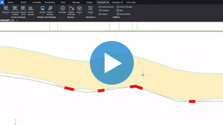
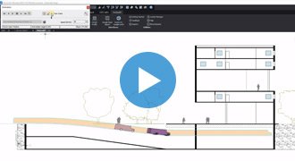
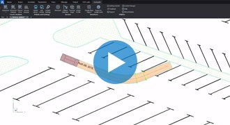
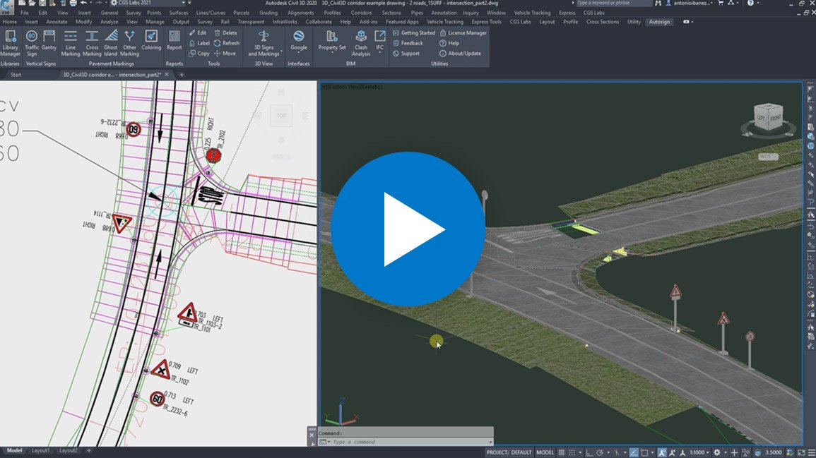
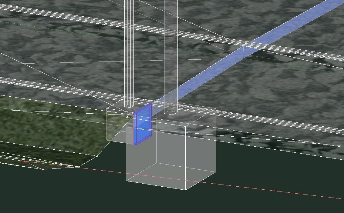
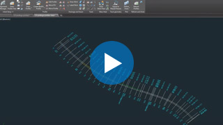
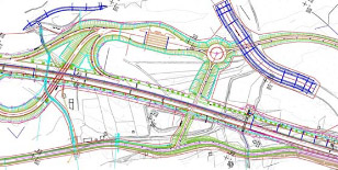
Using the Horizontal or Vertical Analysis feature, you can easily and quickly simulate vehicle maneuvers and check transportability. Autopath works in AutoCAD, Civil 3D or BricsCAD environments. You can check for possible conflicts and inconsistencies of the vehicle path with other vehicles or with built objects. You can also create a steering wheel report – graphic diagram, presenting the intensity of rotation of the vehicle wheels along the vehicle path.

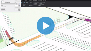


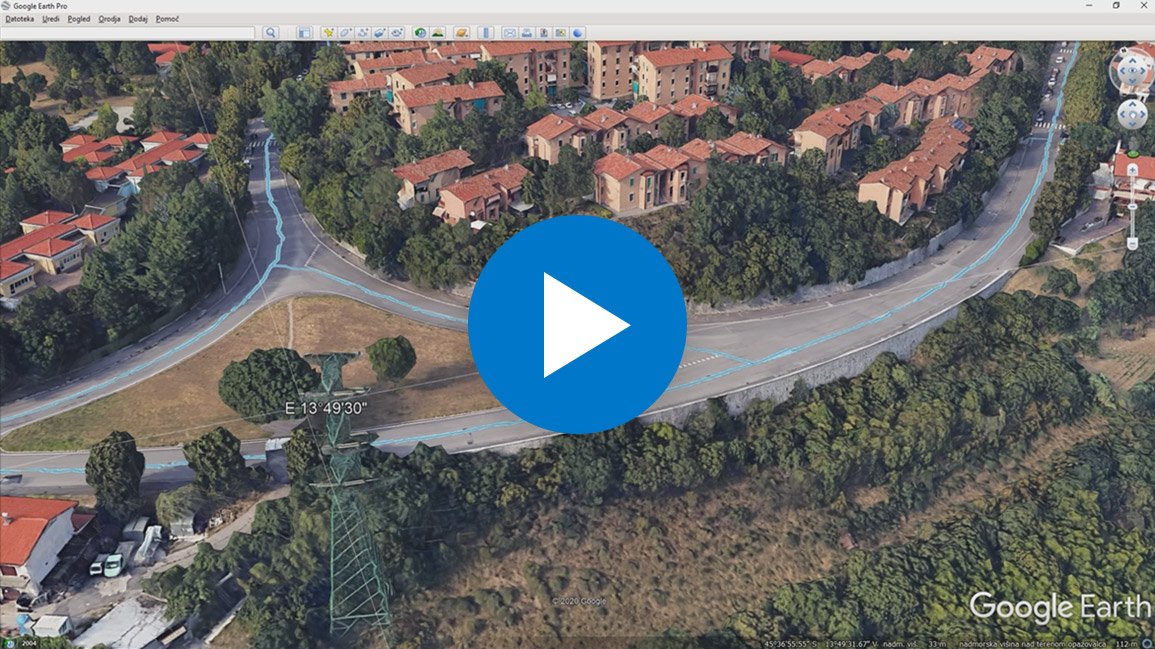
Vehicle movement animations in the form of trajectories that are created in CAD drawing using Autopath can be easily exported to Google Earth. There you can quickly create presentations for the client and the interested public and share your analysis results online, allowing other participants in the project to provide you with quality, up-to-date feedback.
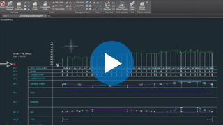
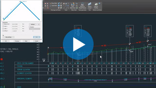
Autopath comes with advanced reporting capabilities for each swept path analysis made. Reports include names and types of used vehicles, vehicle schematics with detailed dimensions, steering wheel turning diagram showing turning angles, turn wheels on stop sections, maximal vehicle steering angle and more. Reports can be exported to PDF and other formats.


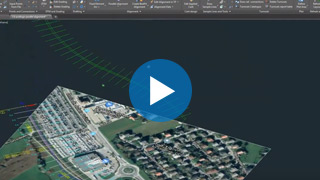
Autopath provides the option to insert raster Imagery and elevation data (Google Earth Surface data) and Street View capabilities within the CAD drawing to help clients, investors, or the interested public to visualize areas where swept path analysis is taking place.
Combining such data with CAD BIM infrastructural or architectural models offers immersive visualization capabilities and great value analysis. Autopath comes with an extensive list of supported coordinate systems worldwide to enable convenient data insertion.

Fields of use
Civil engineering
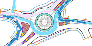
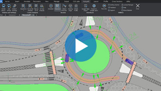
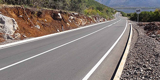
Autopath plays a key role in verifying the transportability of all types of road design projects: on roads, intersections, roundabouts, hairpin turns, underpasses, overpasses, and similar places. With advanced tools for swept path analysis and animation, it not only accelerates the engineering design process but also enables quick checking of alternative design options, as well as safety and compliance with standards.

Special transport
Special transport services require specialized transport vehicles (semi-lowloader trailer, lowbed, mobile cranes, etc.) and tailored transport routes. Autopath includes an extensive library of specialized transport vehicles, all of which can be further customized in detail. You can design any type of vehicle outline that precisely represents the transported load. Autopath supports the use of Google Maps, Google StreetView, and OpenMaps, which is indispensable for evaluating different scenarios of transport routes. With support for all types of cranes, you can virtually plan the transport from factory, cargo port or freight terminal to the target destination.
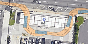
Architectural & Urban Design
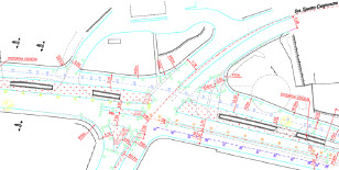
Autopath provides easy-to-use tools for architects and urban planners for analyzing vehicle swept paths in a CAD environment. They can perform simple vehicle maneuvers, carry out turning simulations, and identify potential limitations in the design of garages, parking spaces, intervention routes, etc. With access to a large library of vehicles, architects now have a tool for swept path analysis with which they can accurately, confidently, and independently evaluate their designs.


Construction sites
Autopath is used by civil engineers when planning construction sites and site design projects. They can plan the paths and maneuvers of construction machinery, trucks and other specialized vehicles for transporting construction materials. It allows the planning to take place ahead of time, speeding up the permit stage and allowing for repositioning or replacement of any obstacles along the way.
Aviation
When designing airports, special care is taken to make sure that the airport can adequately service all aircraft, transport cargo, and passengers. That is why engineers, both in the design and operation phase of the airport, carry out various simulations of aircraft maneuvers, vehicle/airplane swept path analysis and check for potential collisions, thereby reducing security risks and ensuring smooth operation. To serve this purpose, Autopath comes with a predefined library of aircraft, as well as intervention and various other vehicles, and can customize vehicles if needed.


Intralogistics
Autopath is a proven useful tool in the process of factory design. Using it, engineers can simulate the transportation of goods on the factory lanes as well as simulate AGV’s (automated guided vehicles) or tugger trains for the transportation of goods on factory grounds. When designing warehouse-racking layouts, Autopath is used to check for possible forklift constraints, evaluate tugger trains’ transportation paths, delivery vehicles maneuvers, and similar.
Fields of use

Civil engineering
Autopath plays a key role in verifying the transportability of all types of road design projects: on roads, intersections, roundabouts, hairpin turns, underpasses, overpasses, and similar places. With advanced tools for swept path analysis and animation, it not only accelerates the engineering design process but also enables quick checking of alternative design options, as well as safety and compliance with standards.
Special transport
Special transport services require specialized transport vehicles (semi-lowloader trailer, lowbed, mobile cranes, etc.) and tailored transport routes. Autopath includes an extensive library of specialized transport vehicles, all of which can be further customized in detail. You can design any type of vehicle outline that precisely represents the transported load. Autopath supports the use of Google Maps, Google StreetView, and OpenMaps, which is indispensable for evaluating different scenarios of transport routes. With support for all types of cranes, you can virtually plan the transport from factory, cargo port or freight terminal to the target destination.
Architecture
Autopath provides easy-to-use tools for architects and urban planners for analyzing vehicle swept paths in a CAD environment. They can perform simple vehicle maneuvers, carry out turning simulations, and identify potential limitations in the design of garages, parking spaces, intervention routes, etc. With access to a large library of vehicles, architects now have a tool for swept path analysis with which they can accurately, confidently, and independently evaluate their designs.
Industrial
Autopath is a proven useful tool in the process of factory design. Using it, engineers can simulate the transportation of goods on the factory lanes as well as simulate AGV’s (automated guided vehicles) or tugger trains for the transportation of goods on factory grounds. When designing warehouse-racking layouts, Autopath is used to check for possible forklift constraints, evaluate tugger trains’ transportation paths, delivery vehicles maneuvers, and similar.
Aviation
When designing airports, special care is taken to make sure that the airport can adequately service all aircraft, transport cargo, and passengers. That is why engineers, both in the design and operation phase of the airport, carry out various simulations of aircraft maneuvers, vehicle/airplane swept path analysis and check for potential collisions, thereby reducing security risks and ensuring smooth operation. To serve this purpose, Autopath comes with a predefined library of aircraft, as well as intervention and various other vehicles, and can customize vehicles if needed.
Supported languages
- Austrian German
- Croatian
- Czech
- English (International)
- English (USA-AASHTO)
- German
- Hungarian
- Polish
- Serbian
- Slovenian
Supported CAD platforms
- Autodesk® AutoCAD® 2018 - 2025 (except AutoCAD LT)
- Autodesk® Civil 3D® 2018 - 2025
- BricsCAD® Pro, BIM and Ultimate V22 – V25
* Only 64-bit versions are supported
- Easy drive (dynamic horizontal vehicle swept path analysis with forward and reverse turn prediction)
- 2D Horizontal vehicle swept path analysis
- 2D Vertical vehicle swept path analysis
- Vehicle manual drive mode
- Vehicle movement animation
- Detection of horizontal and vertical analysis clash points
- Vehicle Library (national, specialized, aircraft and airport utility)
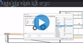
- Options for creating and editing Custom vehicles and Special transports
- Import of Google Maps geospatial data in CAD drawing
- Vehicle steering wheels diagram
- Draw vehicle profile with dimensions
- 3D vehicle animation
- 3D solid vehicle modelling
- Intralogistics vehicle libraries
- Advanced vehicle steering options
- Easy drive (dynamic horizontal vehicle swept path analysis with forward and reverse turn prediction)
- 2D Horizontal vehicle swept path analysis
- 2D Vertical vehicle swept path analysis
- Vehicle manual drive mode
- Vehicle movement animation
- Detection of horizontal and vertical analysis clash points
- Vehicle Library (national, specialized, aircraft and airport utility)
- Options for creating and editing Custom vehicles and Special transports
- Import of Google Maps geospatial data in CAD drawing
- Vehicle steering wheels diagram
- Draw vehicle profile with dimensions
- 3D vehicle animation
- 3D solid vehicle modelling
- Intralogistics vehicle libraries
- Advanced vehicle steering options


PLATEIA Traffic Collection
»PLATEIA Traffic Collection« is a suite of productivity-oriented BIM-ready programs for Site design, Traffic signalization design & planning, and Vehicle swept path analysis. As an add-on to Civil 3D, AutoCAD or BricsCAD, it helps Road designers and Traffic engineers to significantly shorten the time needed to finish their projects.
Watch the webinar | Meet PLATEIA Traffic Collection
Features
SITE DESIGN includes quick site modeling features, earthwork calculation, utility design, and productivity tools to speed up project delivery. It is ideal for fast conceptual projects, solution testing projects, detailed design, and earthwork projects including volume calculation, grading, and more. Serving data for machine control guidance, blueprints project delivery, survey data, and for great visualizations.

Surface
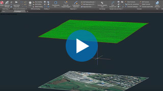
The terrain design is the main benefit of the new collection. Surface can be created based on the survey data or simply imported from Google Maps. The biggest advantage of this surface tool is that it creates ultralight surface models in an instant.
Google Maps & Google Street View
Google Maps Import makes it easy to import raster images and elevation data of a selected location from Google Maps into a DWG drawing in the selected coordinate system. Google Street View functionality is also available to allow the user to view the selected area interactively within the CAD environment.

Google Earth Export
Plateia BIM (3D solid) road infrastructure model can be quickly visualized directly into Google Earth. This allows us to present the project in an environment that enables the user to have exceptional visual performances.

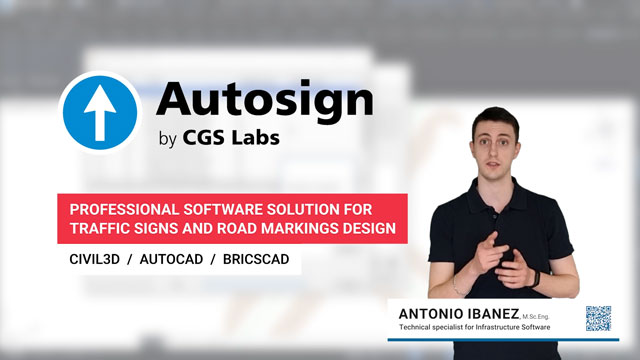
AUTOSIGN is a professional software solution for planning traffic signal design in CAD environments. It generates detailed layouts and reports. AUTOSIGN includes extensive collections of country-specific traffic sign libraries and road markings.
PLATEIA Traffic Collection offers the most capable software option, AUTOSIGN Ultimate.
[read more about Autosign]

AUTOPATH is a professional software for swept path analysis and vehicle turning simulations. With it, you can easily and quickly simulate vehicle manoeuvres and check the transportability of all types of road design projects: on roads, intersections, roundabouts, hairpin turns, underpasses, overpasses, etc.
PLATEIA Traffic Collection offers the most capable software option, AUTOPATH Ultimate.
[read more about Autopath]


Supported languages
- Austrian German
- Croatian
- Czech
- English (International)
- English (USA-AASHTO)
- German
- Hungarian
- Polish
- Serbian
- Slovenian
Supported CAD platforms
- Autodesk® AutoCAD® 2018 - 2025 (except AutoCAD LT)
- Autodesk® Civil 3D® 2018 - 2025
- BricsCAD® Pro, BIM and Ultimate V22 – V25
* Only 64-bit versions are supported
Select the version according to your needs
Available as a standalone or network license
- Survey data import
- Digital terrain modeling tool (CGS Labs DTM)
- 3D Grading
- Support for Civil 3D and BricsCAD surface
- Alignment design
- Profile design
- Cross-sections design
- Road super elevations
- 3D Road modeling
- Points, lines and 3D solids projection to Profile View & Cross Sections Views
- Labeling and dimensioning tools
- Visibility analysis & Stop sight distance
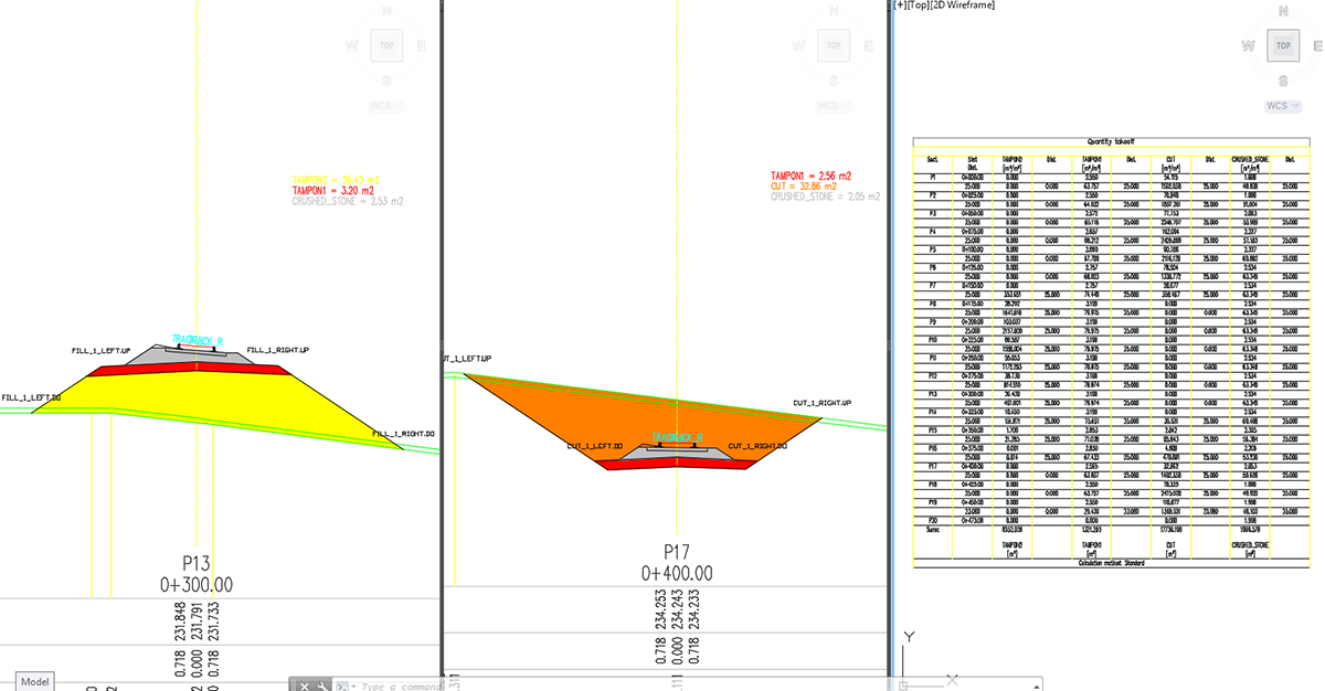
- Quantity Take-off & Mass Haul diagrams
- Intersections design 2D/3D
- Roundabout design
- Intersections islands design
- Curb return fillets
- Interface for Civil 3D objects <-> Plateia
- Regression alignment and profile design (Best-Fit)
- Regression alignment and profile analysis and editing
- Side road objects distance calculation (Off-Set calculation)
- Import of Google Maps geospatial data in CAD drawing
- 2D Traffic signs and road markings design (Autosign Professional)
- 3D/BIM Traffic signs and road markings design & visualization (Autosign Ultimate)
- Vehicle swept path analysis and turning simulation (Autopath Professional)
- Support for 3D Solid objects
- BIM object property tools (manager/editor/filter)
- 3D/BIM object clash analysis within AutoCAD, Civil 3D, and BricsCAD
- Import/Export LandXML data
- Import/Export 3D/BIM model to IFC 4.2 data format
- Export 3D road model to Google Earth
- Survey data import
- Digital terrain modeling tool (CGS Labs DTM)
- 3D Grading
- Support for Civil 3D and BricsCAD surface
- Alignment design
- Profile design
- Cross-sections design
- Road super elevations
- 3D Road modeling
- Points, lines and 3D solids projection to Profile View & Cross Sections Views
- Labeling and dimensioning tools
- Visibility analysis & Stop sight distance
- Quantity Take-off & Mass Haul diagrams
- Intersections design 2D/3D
- Roundabout design
- Intersections islands design
- Curb return fillets
- Interface for Civil 3D objects <-> Plateia
- Regression alignment and profile design (Best-Fit)
- Regression alignment and profile analysis and editing
- Side road objects distance calculation (Off-Set calculation)
- Import of Google Maps geospatial data in CAD drawing
- 2D Traffic signs and road markings design (Autosign Professional)
- 3D/BIM Traffic signs and road markings design & visualization (Autosign Ultimate)
- Vehicle swept path analysis and turning simulation (Autopath Professional)
- Support for 3D Solid objects
- BIM object property tools (manager/editor/filter)
- 3D/BIM object clash analysis within AutoCAD, Civil 3D, and BricsCAD
- Import/Export LandXML data
- Import/Export 3D/BIM model to IFC 4.2 data format
- Export 3D road model to Google Earth
References
Building the future together


Autosign, traffic signs & road markings design

2D/3D/BIM traffic signal design planning
Autosign is a professional software solution for planning traffic signal design in Civil3D, AutoCAD, or BricsCAD. It generates detailed documentation, layouts, and reports. It generates detailed layouts, reports, 3D (BIM) objects, and realistic visualizations.

Libraries of traffic signs and road markings
Autosign includes extensive collections of country-specific traffic sign libraries and road markings.

Intuitive user interface
Autosign’s carefully designed user interface and workflows make it consistently user-friendly software.
Features
Autosign provides several country-specific road-signaling libraries defined by national guidelines, including traffic signs, longitudinal road markings, crossing road markings, and various other pavement markings.
Users also have an advanced option to create a custom library of their own traffic signs blocks and use them in the designs with the same features that are available with the original Autosign signs.
Available localized libraries of country-specific traffic signs and road marking with 3D/BIM support:
| USA | American Manual on Uniform Traffic Control Devices (MUTCD) and its companion volume the Standard Highway Signs (SHS) |
| AUSTRALIA | Australian Manual on Uniform Traffic Control Devices (MUTCD) |
| AUSTRIA | Austrian legislation (Bundesgesetz vom 6. Juli 1960, mit dem Vorschriften über die Straßenpolizei erlassen werden (Straßenverkehrsordnung 1960 – StVO. 1960)) |
| BOSNIA AND HERZEGOVINA | Bosnian legislation (Pravilnik o saobraćajnim znakovima i signalizaciji na cestama, načinu obilježavanja radova in prepreka na cesti in znakovima koje učesnicima v saobraćaju daje ovlašćena osoba, 2017) |
| BULGARIA | Bulgarian legislation (Road traffic signs. Dimensions and letters. Bulgarian Standard BDS 1517) |
| CROATIA | Croatian legislation (Pravilnik o prometnim znakovima signalizaciji in opremi na cestama NN 92-19, 2019) |
| CZECH REPUBLIC | Czech legislation (Vyhláška, kterou se provádějí pravidla provozu na pozemních komunikacích, 2015) |
| CZECH RAIL | Library of rail signals. |
| ESTONIA | Estonian legislation (EVS613:2001, EVS614:2008) |
| GERMANY | German legislation (Verkehrszeichenkatalog, 2017. Letzte Aktualisierung 06/2024) |
| LATVIA | Latvian legislation (Ceļu satiksmes noteikumi, 2015) |
| LITHUANIA | Lithuanian legislation (Kelio ženklų įrengimo in vertikaliojo ženklinimo taisykles. Žin., 2008, Nr. 46-1730. 2012.) |
| NEW ZEALAND | New Zealand legislation (Traffic Control Devices Manual) |
| ROMANIA | Romanian legislation (Standard Român ASRO. SR 1848 – 1, 2024 & SR 1848 7 2015) |
| POLAND | Polish legislation (Rozporządzenie w sprawie znaków i sygnałów drogowych (Dz.U. z 2019 r. poz. 2310)) |
| QATAR | Library of traffic signs based on the Qatar Traffic Control Manual (QTCM) |
| SERBIA | Serbian legislation (Pravilnik o saobracajnoj signalizaciji, 2017) |
| SLOVENIA | Slovenian legislation (Pravilnik o prometni signalizaciji in prometni opremi na cestah, 2024) |
| SWEDEN | Swedish legislation (Transportstyrelsens Författningssamling | TSFS 2019:74 | TSFS 2010:171 | TSFS 2014:30) |
| SLOVENIA – VARNEJE V SOLO | Varneje v šolo (Smernice za postavitev in izvedbo urbane opreme ter arhitekturnega oblikovanja prometnih površin za izboljšanje prometne varnosti otrok – šolarjev) |
When you are working on road design projects in either Civil 3D, AutoCAD or BricsCAD, Autosign can be used to draw and plan a complete road signalization and prepare the necessary documentation.
You can link Autosign signaling elements (traffic signs and road markings) to the information of your Civil 3D alignment, or any other Polyline alignment in your drawing.


Parking lot design tool enables a parametric design of parking lots. To speed up the design process, Autosign provides a wide variety of floor markings that can be assigned to the design: single lines, double lines, dashed lines, coloring, and many more. Users can either take advantage of the predefined markings that are specific to individual countries* or they can choose to define markings with custom parameters that can be saved for repeated use.
All floor markings created with Autosign can be projected on the road surface or any other surface of the DTM, creating 3D floor markings, with assigned BIM properties.
The parking lot design report is another handy feature that will provide you with a detailed table of quantities which can be either included directly in the design or exported to XLS format for further use.


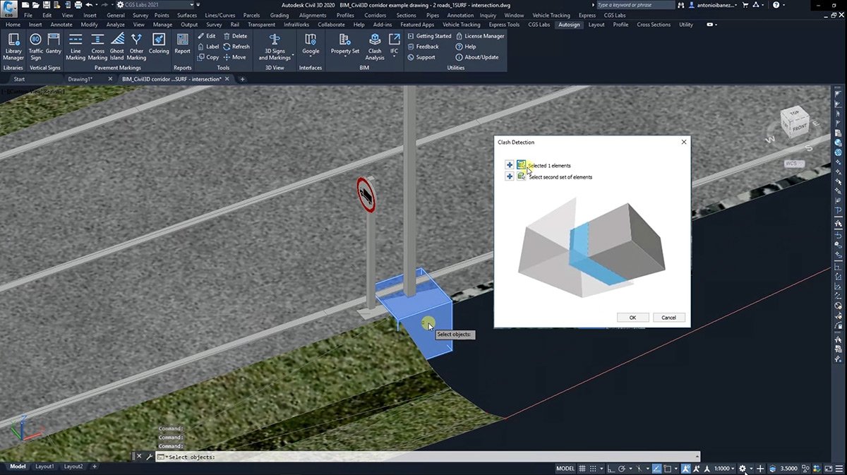
Autosign creates traffic signs, portals, road markings, and other side road objects as BIM objects (3D solid objects with assigned Property Set data), that can be viewed and manipulated in Autodesk Navisworks and InfraWorks or exchanged through the IFC 4.2 file format to be used in any BIM-ready software solution.

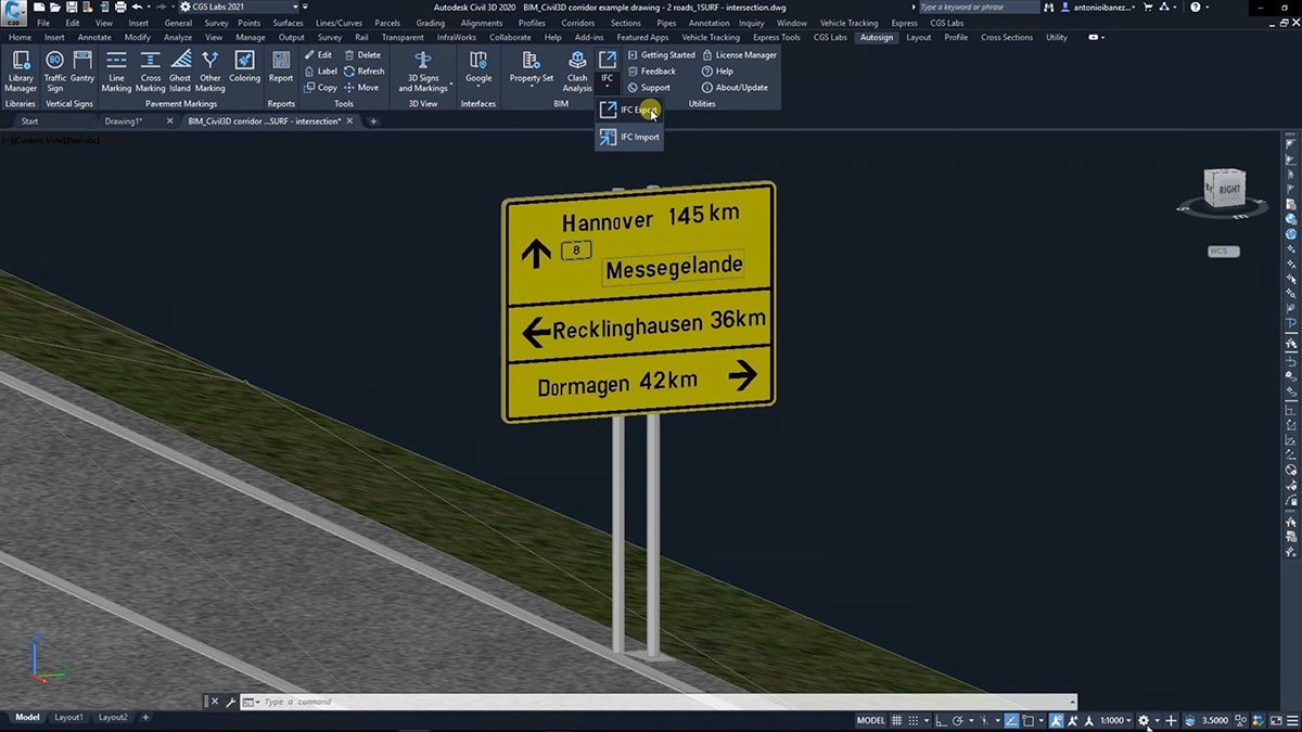

Autosign provides the option to import earth surface data (raster imagery and elevation data) from Google Maps directly into your CAD drawing to help visualize areas where the projects are located.
You can also export your 3D designs directly to Google Earth. In this way, you can create accurate visualizations on the exact location of the project.
Fields of use
Infrastructure design
- Roadways
- Pedestrian areas
- Bicycle networks
- Urban areas


Traffic management
Use Autosign for planning traffic signs and road markings in both urban and inter-urban road infrastructure, redesigning the traffic flow or implementing new practical solutions to any problem that traffic engineers may face.
Road works and Temporary Situations
Indicate lane closures and road works, create diversion paths, set safety and visible limits for pedestrian sidewalks and manage the signaling of every temporary situation that occurs in your project.


Car parking areas
Autosign provides tools to design details of parking facilities, such as delimitation lines, vertical signaling, height control gantries, and more.
Warehouse traffic design and management
Design signaling for indoor and outdoor traffic, warning and restricted areas for warehouses, production facilities, and industrial areas.

Cycle path network design
Urban planners will be able to shape every pavement marking and vertical sign to design sustainable cycle path networks, as well as to paint the paths or other elements.
Ski resort & Sport centre design
Facilities designers will discover in Autosign a product to design the requested signaling for ski slopes, as well as floor markings for courts and pitches of any sport – even running tracks.


Motor-racing circuits & Safety driving centre design
Design the signaling and equipment at the highest level in term of competition and safety.
Fields of use
Infrastructure design
- Roadways
- Pedestrian areas
- Bicycle networks
- Urban areas
Traffic management
Use Autosign for planning traffic signs and road markings in both urban and inter-urban road infrastructure, redesigning the traffic flow or implementing new practical solutions to any problem that traffic engineers may face.
Road works and Temporary Situations
Indicate lane closures and road works, create diversion paths, set safety and visible limits for pedestrian sidewalks and manage the signaling of every temporary situation that occurs in your project.
Car parking areas
Autosign provides tools to design details of parking facilities, such as delimitation lines, vertical signaling, height control gantries, and more.
Warehouse traffic design and management
Design signaling for indoor and outdoor traffic, warning and restricted areas for warehouses, production facilities, and industrial areas.
Cycle path network design
Urban planners will be able to shape every pavement marking and vertical sign to design sustainable cycle path networks, as well as to paint the paths or other elements.
Ski resort & Sport centre design
Facilities designers will discover in Autosign a product to design the requested signaling for ski slopes, as well as floor markings for courts and pitches of any sport – even running tracks.
Motor-racing circuits & Safety driving centre design
Design the signaling and equipment at the highest level in term of competition and safety.
Supported languages
- Austrian German
- Croatian
- Czech
- English
- German
- Hungarian
- Polish
- Serbian
- Slovenian
Supported CAD platforms
- Autodesk® AutoCAD® 2018 - 2025 (except AutoCAD LT)
- Autodesk® Civil 3D® 2018 - 2025
- BricsCAD® Pro, BIM and Ultimate V22 – V25
* Only 64-bit versions are supported
Functionalities
Available as a standalone or network license
- Access to national libraries of traffic signs and road markings
- Traffic signs design
- Custom traffic signs
- Gantry design
- Pavement markings design (line markings, cross markings, ghost islands, arrows, etc.)
- Coloring of pavement areas
- Reports of traffic signs and road markings (with quantities)
- Import of earth surface data from Google Maps
- 3D traffic signs and road markings
- Export 3D designs to Google Earth
- Support for 3D Solid objects (compatible with InfraWorks and Navisworks)
- BIM tools (Property set Manager / Editor / Filter)
- Clash Analysis within AutoCAD, Civil 3D, and BricsCAD
- Import & Export to IFC 4.2 file format for data exchange with other BIM software

Autopath, vehicle swept path analysis and turn simulation
Vehicle swept path analysis & 3D animation
Autopath is a professional software solution for vehicle swept path analysis used by civil engineers, transportation professionals, architects, and urban planners. Autopath enables the simulation and analysis of vehicle manoeuvres, 3D vehicle animation and more.
Intuitive user interface
Autopath is distinguished by its carefully designed UI and workflow that make it fast to learn and easy to use. Competitive pricing, service for designing complex custom vehicles, and high-level technical support make Autopath the product of choice for professionals worldwide.
Our Customers’ Journey
Vehicle libraries
![]() AUTOPATH includes several country-specific reference vehicle libraries defined by national guidelines, and an extended collection of vehicles from different manufacturers, covering aircraft, buses, cranes, emergency vehicles, trucks, agricultural machinery and more.
AUTOPATH includes several country-specific reference vehicle libraries defined by national guidelines, and an extended collection of vehicles from different manufacturers, covering aircraft, buses, cranes, emergency vehicles, trucks, agricultural machinery and more.
| USA / CANADA / INDIA | AASHTO 2014 (Imperial / Metric), AASHTO 2011 (Imperial / Metric) |
| CANADA | TAC 2017 |
| EUROPE | United Kingdom (FTA 2016, FTA 1998) |
| Irish national vehicle library | |
| Germany (Deurschland 2005), Deutschland RBSV_2020 | |
| Austria (Österreich) | |
| Sweden (Sverige 2005) | |
| Norwegian (Norge 2007) | |
| Poland (Polska 2016) | |
| Hungary (Magyarország 2005) | |
| Czech Republic (TP 171, 2005) | |
| Croatia (Hrvatska 2001) | |
| Serbia (Serbia 2012) | |
| Slovenia (Slovenija 2006) | |
| Romania (Romania 1985) | |
| North Macedonia | |
| Turkey (Türkiye) | |
| RUSSIA | POCCŃЯ |
| AUSTRALIA | Australia 1993, Australia 2013, Australia 2018 |
| NEW ZEALAND | New Zealand 2007 Auckland Transport 2022 Auckland Transport 2016 |
| AFRICA | South Africa (South Africa 1988), Tanzanai (TANZANIA_2011) |
| UAE | UAE (United Arab Emirates 2017) |
| ISRAEL | Israel (Israel 2011) |
In the latest version, Autopath gets an extensive number of vehicle libraries and utility vehicle types added to the existing vehicle list, vehicle types ranging from agricultural vehicles, emergency vehicles, buses, trucks, trailers for wind turbine transport, cranes, forklifts and more.
| BUS | Ikarus, Kravtex, Man, Mercedes, Neoplan, Rába, Setra, Volvo |
| CRANE KATO | CR-100, CR-250, MR-130, NK-300E-v, NK550vr ► we support vehicles with all wheels steering |
| CRANE LIEBHERR | LTM1030-2.1, LTM1040-2.1, LTM1050-3.1, LTM1055-3.2, LTM1060-3.1, LTM1070-4.2, LTM1090-4.1, LTM1100-5.1, LTM1100-5.2, LTM1350-6.1, LMT1250-5.1 ► we support vehicles with all wheels steering |
| CRANE TEREX | AC55-3 (385/95R25) AWS(3), AC55-3 (445/95R25) AWS (3), AC60-3 (385/95R25) AWS(3), AC60-3 (445/95R25) AWS (3), AC140 (385/95R25) ASW (3), AC140 (445/95R25) AWS(3), AC160-2 (385/95R25), AC160-2 (445/95R25), AC160-5 (385/95R25) AWS (3), AC160-5 (445/95R25) AWS (3), AC160-5 (525/80R25) AWS (3), AC250-1 (525/80R25), TEREX MAX 25 ► we support vehicles with all wheels steering |
| CUSTOM | Wind Transport, Heavy Load Vehicle, Long Cargo Vehicle |
| EMERGENCY EUROPE | Mercedes Benz, Tatra, Man, Iveco |
| EMERGENCY AASHTO | Fire Vehicle – Pumper, Fire Vehicle – Aerial Platform |
| GOLDHOFER | Drop-Deck Semitrailler, Europe Flatbad, Flatbad with Pendular Axles |
| MINING TRUCKS CAT | 785D, 770G, 797F, 772G, 773G, 775G, 777G, 789D, 793D, 793F, 794AC, 796AC, 798AC |
| MINING TRUCKS KOMATSU | HD325-7R, HD465, HD465, 730E, 830E-AC, 860E-1K, 930E-4, 930E-4SE, 960E-1, HD1500-7, HM300-2R (ARTICULATED), HM400-3R (ARTICULATED) |
| EMERGENCY SLO | PV-1, PV-2, GV-1, GVV-1, GVV-2, GVC-16/15, GVC-16/25, GV-16/24, GVC-24/50, AC, GVGP-1, GVGP-2 |
| TRUCK | Mercedes Benz, Iveco, MAN |
| WHEEL LOADER | Sonnebogen 355 E, LIEBHER_L544, LIEBHER_L506compact, LIEBHER_L585, MLT 741-140 V+, MLT 961-160 V+L, MLT 741-130 PS+, STEYR_6125, STEYR_6125 + CMC-ST-300, VOLVO (L110H, L120H, L50H) |
| CONCRETE MIXER | MAN TGS 41.420 8×4; ITAS CAS |
| AGRICULTURAL MACHINERY | Tractor John Deere 5603 4WD, Tractor Fendt 936 Vario, Tractor + Bailey Dumper DUMP10, Tractor + Bailey Grain Trailer TAG11, Tractor + Bailey Baby Trailer BR2.0, Tractor + Bailey Low Loader LOW 8/16 |
| AMBULANCE EUROPE | TYPE A, TYPE A2, TYPE B, TYPE B1, TYPE C |
| BICYCLE | Normalrad, Muli Pendix, Douz G4 Traveller, Christiana |
| BULKCEMENT TRAILER | PREPRAVNIKY NCJ 32, PREPRAVNIKY NCJ 36, PREPRAVNIKY NCJ 40, PREPRAVNIKY NCJ 45, PREPRAVNIKY NCJ 46, PREPRAVNIKY NCJ 54, SKLOPNE PREPRAVNIKY |
| PICK UP TRUCK | Ford Ranger, Toyota HiLux, Nissan Navara, Mercedes Benz X, Isuzu D-Max, Volkswagen Amarok, Mitsubishi L200, Ford F-150 |
| REFUSE EUROPE | Phoenix 2 Duo (P2-12W, P2-15W), Phoenix 2 (Twin Pack 15, (Twin Pack 20), Phoenix 2 (One-Pass), Phoenix 2-09N, Phoenix 2-12N, Phoenix 2-12W, Phoenix 2-15N (6×2 ML, 6×2 MS, 6×2 RS), Phoenix 2-15W (6x2ML ,4×2), Phoenix 2-17N (6×2 ML, 6×2 MS, 6×2 RS), Phoenix 2-18W (6x2ML, 6x2MS, 6x2RS, 6×4), Phoenix 2-20W (6x2MS, 6×4, 6×2 RS, 6x2ML), Phoenix 2-23W (6x2MS, 6×4, 6×2 RS, 6x2ML), Phoenix 2-25W, Phoenix 2 Duo Kitchen, Phoenix 2 Duo Recycler, hoenix 2 High Capacity (Twin Pack 15, Twin Pack 20, Twin Pack 50/50), Phoenix 2 One-Pass, Small Refuse Vehicle, Vulture 2225 |
| SUV | Audi Q8, BMW X7, Mercedes Benz GLS, Volkswagen Touareg, Volvo XC90, Land Rover Range Rover, Škoda Kodiaq, Škoda Kamiq, Rolls Royce Cullinan |
| AMBULANCE DEMERS | MXP 150 (Ford 350), MXP 170 (Ford F-550), EX SPRINTER 2500, MX 151 (Ford E350), TRANSIT T250/T350, MX 152 (Mercedes-Benz), MX 170 (Cheverlet Express 4500), MX 164 (Cheverlet Express 3500), MX 164 (Ford E350), MX 170 (Ford E450) |
| MILITARY IVECO | CENTAURO II, CENTAURO I, VBM_FRECCIA_AIFV/ATGM, CENTAURO AIF/OWS 30, VBM FRECCIA AMC, VBM FRECCIA ARV, VBA Amphibious Armoured Vehicle, Puma 4×4, Puma 6×6, LMV 2, LMV MEDEVAC, Medium Protected Vehicle 4×4, Medium Protected Vehicle 6×6, M170.31/33, M250.40/41/45 WM, M320.45 WM |
| AIRCRAFT | Boeing 737-700, Boeing 737-400 |
| AIRCRAFT AIRBUS | A380-800, A340-600, A340-500, A350-900, A340-300, A330-300, A320-200 |
| AIRCRAFT BOEING | 747-8, 747-400, 777-300ER, 777-200LR, 737-700, 737-400, 707-120, 707-320, 717-200, 727-100, 727-200, 737-100, 737-200, 737-300, 737-500, 737-600, 737-800, 737-900, 737-MAX 7, 737-MAX 8, 737-MAX 9, 737-MAX 10, 747-100B-200-300, 747SP, 747-8F, 757-200, 757-300, 767-200, 767-300, 767-400ER, 777-9, 787-8, 787-9 |
| APRON BUS | TAM_VIVIAIR60S, TAM_VIVIAIR72M, TAM_VIVIAIR84L, TAM_VIVIAIRE88W, TAM_VIVIAIR104WL |
| AIRSTAIRS | TLD ABS-580 |
| BAGGAGE TRANSFER | TLD JST-25 |
Analysis Tools & Reports
Using the Horizontal or Vertical Analysis feature, you can easily and quickly simulate vehicle maneuvers and check transportability. Autopath works in AutoCAD, Civil 3D or BricsCAD environments. You can check for possible conflicts and inconsistencies of the vehicle path with other vehicles or with built objects. You can also create a steering wheel report – graphic diagram, presenting the intensity of rotation of the vehicle wheels along the vehicle path.
Vehicle movement animations in the form of trajectories that are created in CAD drawing using Autopath can be easily exported to Google Earth. There you can quickly create presentations for the client and the interested public and share your analysis results online, allowing other participants in the project to provide you with quality, up-to-date feedback.
Autopath comes with advanced reporting capabilities for each swept path analysis made. Reports include names and types of used vehicles, vehicle schematics with detailed dimensions, steering wheel turning diagram showing turning angles, turn wheels on stop sections, maximal vehicle steering angle and more. Reports can be exported to PDF and other formats.
Autopath provides the option to insert raster Imagery and elevation data (Google Earth Surface data) and Street View capabilities within the CAD drawing to help clients, investors, or the interested public to visualize areas where swept path analysis is taking place.
Combining such data with CAD BIM infrastructural or architectural models offers immersive visualization capabilities and great value analysis. Autopath comes with an extensive list of supported coordinate systems worldwide to enable convenient data insertion.
Fields of use
Civil engineering
Autopath plays a key role in verifying the transportability of all types of road design projects: on roads, intersections, roundabouts, hairpin turns, underpasses, overpasses, and similar places. With advanced tools for swept path analysis and animation, it not only accelerates the engineering design process but also enables quick checking of alternative design options, as well as safety and compliance with standards.
Special transport
Special transport services require specialized transport vehicles (semi-lowloader trailer, lowbed, mobile cranes, etc.) and tailored transport routes. Autopath includes an extensive library of specialized transport vehicles, all of which can be further customized in detail. You can design any type of vehicle outline that precisely represents the transported load. Autopath supports the use of Google Maps, Google StreetView, and OpenMaps, which is indispensable for evaluating different scenarios of transport routes. With support for all types of cranes, you can virtually plan the transport from factory, cargo port or freight terminal to the target destination.
Architectural & Urban Design
Autopath provides easy-to-use tools for architects and urban planners for analyzing vehicle swept paths in a CAD environment. They can perform simple vehicle maneuvers, carry out turning simulations, and identify potential limitations in the design of garages, parking spaces, intervention routes, etc. With access to a large library of vehicles, architects now have a tool for swept path analysis with which they can accurately, confidently, and independently evaluate their designs.
Construction sites
Autopath is used by civil engineers when planning construction sites and site design projects. They can plan the paths and maneuvers of construction machinery, trucks and other specialized vehicles for transporting construction materials. It allows the planning to take place ahead of time, speeding up the permit stage and allowing for repositioning or replacement of any obstacles along the way.
Aviation
When designing airports, special care is taken to make sure that the airport can adequately service all aircraft, transport cargo, and passengers. That is why engineers, both in the design and operation phase of the airport, carry out various simulations of aircraft maneuvers, vehicle/airplane swept path analysis and check for potential collisions, thereby reducing security risks and ensuring smooth operation. To serve this purpose, Autopath comes with a predefined library of aircraft, as well as intervention and various other vehicles, and can customize vehicles if needed.
Intralogistics
Autopath is a proven useful tool in the process of factory design. Using it, engineers can simulate the transportation of goods on the factory lanes as well as simulate AGV’s (automated guided vehicles) or tugger trains for the transportation of goods on factory grounds. When designing warehouse-racking layouts, Autopath is used to check for possible forklift constraints, evaluate tugger trains’ transportation paths, delivery vehicles maneuvers, and similar.
Fields of use
Civil engineering
Autopath plays a key role in verifying the transportability of all types of road design projects: on roads, intersections, roundabouts, hairpin turns, underpasses, overpasses, and similar places. With advanced tools for swept path analysis and animation, it not only accelerates the engineering design process but also enables quick checking of alternative design options, as well as safety and compliance with standards.
Special transport
Special transport services require specialized transport vehicles (semi-lowloader trailer, lowbed, mobile cranes, etc.) and tailored transport routes. Autopath includes an extensive library of specialized transport vehicles, all of which can be further customized in detail. You can design any type of vehicle outline that precisely represents the transported load. Autopath supports the use of Google Maps, Google StreetView, and OpenMaps, which is indispensable for evaluating different scenarios of transport routes. With support for all types of cranes, you can virtually plan the transport from factory, cargo port or freight terminal to the target destination.
Architecture
Autopath provides easy-to-use tools for architects and urban planners for analyzing vehicle swept paths in a CAD environment. They can perform simple vehicle maneuvers, carry out turning simulations, and identify potential limitations in the design of garages, parking spaces, intervention routes, etc. With access to a large library of vehicles, architects now have a tool for swept path analysis with which they can accurately, confidently, and independently evaluate their designs.
Industrial
Autopath is a proven useful tool in the process of factory design. Using it, engineers can simulate the transportation of goods on the factory lanes as well as simulate AGV’s (automated guided vehicles) or tugger trains for the transportation of goods on factory grounds. When designing warehouse-racking layouts, Autopath is used to check for possible forklift constraints, evaluate tugger trains’ transportation paths, delivery vehicles maneuvers, and similar.
Aviation
When designing airports, special care is taken to make sure that the airport can adequately service all aircraft, transport cargo, and passengers. That is why engineers, both in the design and operation phase of the airport, carry out various simulations of aircraft maneuvers, vehicle/airplane swept path analysis and check for potential collisions, thereby reducing security risks and ensuring smooth operation. To serve this purpose, Autopath comes with a predefined library of aircraft, as well as intervention and various other vehicles, and can customize vehicles if needed.
Supported languages
- Austrian German
- Croatian
- Czech
- English (International)
- English (USA-AASHTO)
- German
- Hungarian
- Polish
- Serbian
- Slovenian
Supported CAD platforms
- Autodesk® AutoCAD® 2018 - 2025 (except AutoCAD LT)
- Autodesk® Civil 3D® 2018 - 2025
- BricsCAD® Pro, BIM and Ultimate V22 – V25
* Only 64-bit versions are supported
- Easy drive (dynamic horizontal vehicle swept path analysis with forward and reverse turn prediction)
- 2D Horizontal vehicle swept path analysis
- 2D Vertical vehicle swept path analysis
- Vehicle manual drive mode
- Vehicle movement animation
- Detection of horizontal and vertical analysis clash points
- Vehicle Library (national, specialized, aircraft and airport utility)
- Options for creating and editing Custom vehicles and Special transports
- Import of Google Maps geospatial data in CAD drawing
- Vehicle steering wheels diagram
- Draw vehicle profile with dimensions
- 3D vehicle animation
- 3D solid vehicle modelling
- Intralogistics vehicle libraries
- Advanced vehicle steering options
Aquaterra, BIM software for channel and river works design

BIM Channel/River engineering design
Aquaterra is a professional software for channel and river engineering design. It integrates MIKE 11 and HEC-RAS hydraulic calculations with flood protection design, torrent and landslide control, and irrigation systems design. Using its flexible, dynamic data model, it supports BIM workflows and processes, and IFC standardized data format.
Intuitive user interface
Carefully designed UI and workflows are consistent with the engineering practices. This makes Aquaterra surprisingly fast-to-learn and easy-to-use.

From preliminary to detailed design
Aquaterra facilitates design in all stages of the project, from conceptual studies to detailed design. From the river axis, longitudinal and cross-sections data, user can quickly build a 3D Solid model of river bed and river bank, calculate quantities, and prepare printed documentation.
Features
 CGS Labs solutions provide extensive BIM data support not limited to CAD platforms in use. 3D roadway, railway or river channel models are generated as detailed 3D solid objects with extended BIM metadata attached to objects, or as multiple surfaces for use with computer guided machines etc..
Aquaterra offers capable Property Manager for adding and changing 3D solids property data, which enables COBie (Construction Operations Building Information Exchange) compatibility.
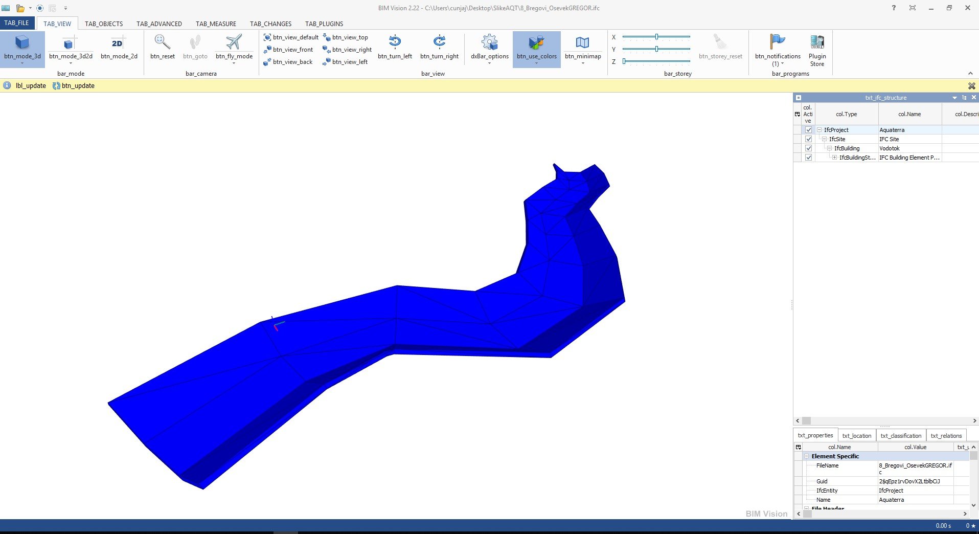
Aquaterra 3D models and attribute data can be exported to IFC files. IFC export format is regularly updated according to buildingSMART International specifications.
Clash detection tool enables designer to search for possible collisions among selected 3D solid objects within the drawing itself thus saving the time to export models and create clash analysis in third party applications outside CAD environment.

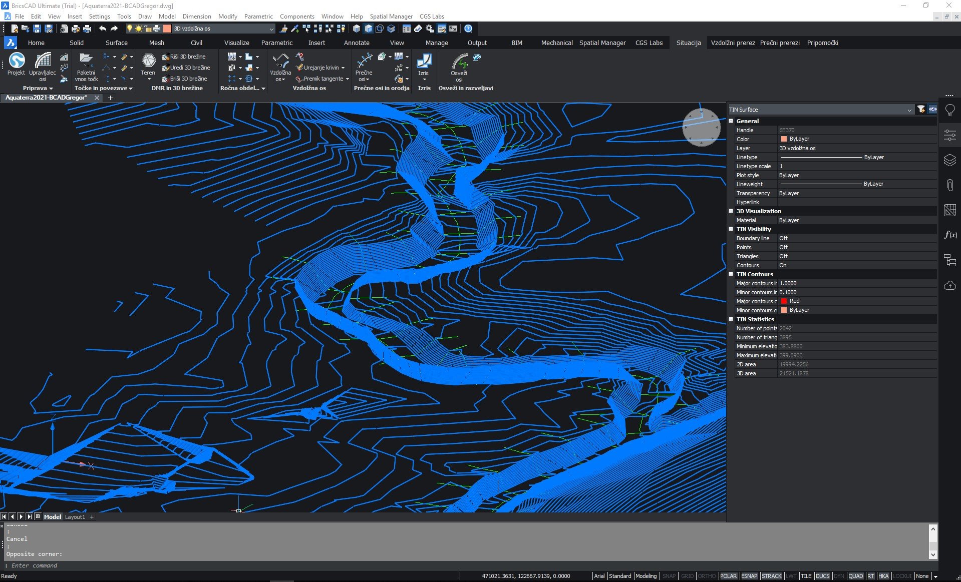
Digital Terrain Modeling
The Surface creation tool is included in CGS Labs software to produce a detailed Digital Terrain Model (DTM) based on various surveys or other input data: total station data files, points, break lines, blocks, etc. This offers the possibility to use Aquaterra on plain AutoCAD or BricsCAD. Aquaterra supports also surfaces from Civil 3D and BricsCAD (V20 or newer).

Grading
Creation of complex slopes with multiple conditions in cut or fill gives users the capability to cover various design scenarios and geometry requirements for all kind of road projects, from simple forest road design to complex intersection geometry design. Furthermore, creating ponds, parking areas, platforms, road, rail tracks, river channels, and other features is easier and faster with CGS Labs grading functionality.
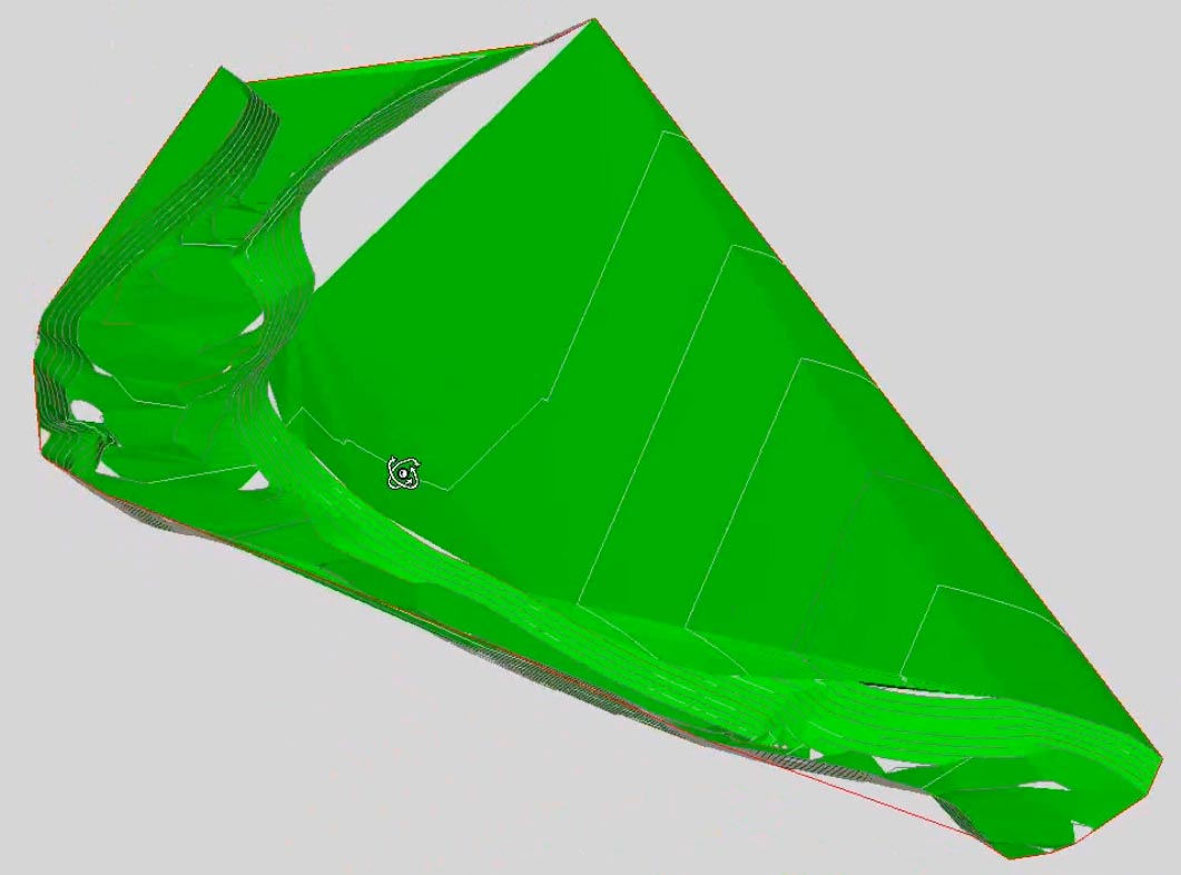
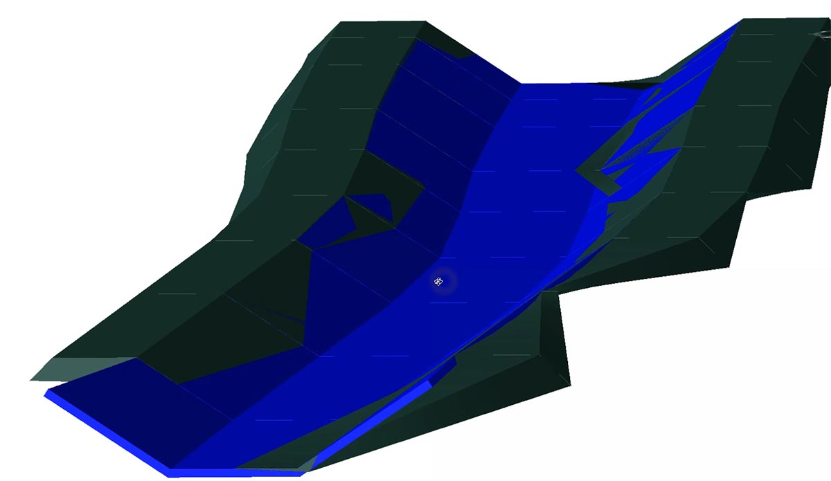
3D Surface and 3D Solid Model
Channel and river bed 3D model can be created as 3D surface or 3D solid model. 3D surface model can be generated automatically from 3D channel or river bed cross sections definition and terrain model, or it can be built with the grading function. 3D solid model is created on the basis of cross-section areas, with materials and volumes defined as extended data. All solid models, including extended data, can be imported into Autodesk Infraworks, Navisworks and can be used in various BIM workflows.
River alignment design tools
Aquaterra provides a wide range of advanced alignment, profile geometry design, and editing tools. They include P(V)I design, floating and fixed elements design, alignment design created from the existing polyline, or ultimately creating a best-fit alignment based on existing channel or river bed survey data. A number of alignment labels, reports and data export options give you the flexibility to cover a wide range of user requirements.

Water level representation and smart lines definition
Water level lines represent data obtained from hydraulic calculation software (MIKE 11 or HEC-RAS). They are displayed relative to the specific alignment in the drawing. To present side objects like channels, dykes, property limits, etc., you can define smart lines in the layout and project them to profile and/or cross section views. The Smart lines functionality is connected with the point’s projection, which offers similar projection options, but dedicated to point objects along any alignment.

Cross sections design and editing capabilities
Enter 1D, 2D water levels or combined calculations and design new or edit existing channel and river bed cross sections geometry. Add dykes and other objects using the large set of tools available. Recalculate water levels and check geometry changes impact for accurate project evaluation.
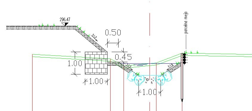

River groins
Groins are a rigid hydraulic structures built from a bank in rivers that interrupt water flow and limit the movement of sediment. Aquaterra supports design of groins along selected banks as 2D elements with varying gradient values.

Quantity take-off (QTO)
Aquaterra calculates material quantity take-off and features a QTO data export tool with custom defined Pay Item (Bill of materials) options. It gives users the possibility to link material defined in the drawing with a material database in cost estimate software, thus supporting digital data transfer and fast cost recalculation when project changes arise.

Mass Haul Diagram
Mass haul diagram presents a graphical view of the material moved in the proposed design site. Mass haul diagrams help designers and contractors understand where gross material movements occur and compare the economies of alternative designs.
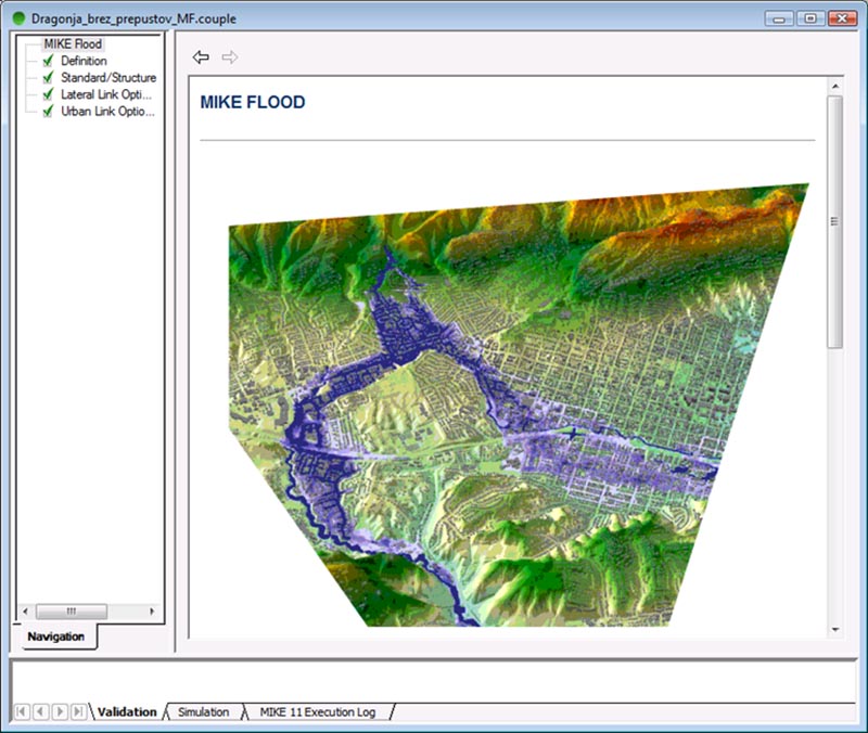
MIKE 11 by DHI is an advanced professional flood modeling solution that enables simulation of any flood problem. It can involve rivers, floodplains, flooding in streets, drainage networks, coastal areas, dams, levee and dike breaches, or any combination of these.
Aquaterra’s integrated MIKE 11 interface transfers graphical data into MIKE 11 where water flow calculations are made. These results are transferred back into Aquaterra where water levels can be displayed in profile and cross section.
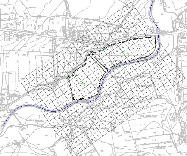
MIKE 11 2D results (floodplain lines) export to Aquaterra is also supported for drawing production within the CAD environment.
HEC-RAS is an established software for one-dimensional steady flow and two-dimensional unsteady flow hydraulic calculations.
Aquaterra’s integrated HEC-RAS interface enables the transfer of channel or river geometry from a CAD environment into HEC-RAS where water flow calculations are made. Calculation results can be transferred back into Aquaterra where calculated water levels are displayed in profile and cross sections. Taking into account the results, engineers can now modify existing channel or river topography, using Aquaterra’s advanced cross-section design and editing tools.
Through Aquaterra’s interface, geometry can also be imported directly from HEC-RAS, edited in Aquaterra and sent back to HEC-RAS for further analysis.

Google Maps & Google Street View
Google Maps Import makes it easy to import raster images and elevation data of a selected location from Google Maps into a DWG drawing in the selected coordinate system. Google Street View functionality is also available to allow the user to view the selected area interactively within the CAD environment.
Google Earth Export
BIM (3D solid) model of the infrastructure can be quickly visualized directly into Google Earth. This allows us to present the project in an environment that enables the user to have exceptional visual performances.
Supported languages
- English
- German
- Croatian
- Serbian
- Slovenian
Supported CAD platforms
- Autodesk® AutoCAD® 2018 - 2025 (except AutoCAD LT)
- Autodesk® Civil 3D® 2018 - 2025
- BricsCAD® Pro, BIM and Ultimate V22 – V25
* Only 64-bit versions are supported
Select the version according to your needs
Available as a standalone or network license
- Survey data import
- Digital terrain modeling tool (CGS Labs DTM)
- 3D Grading
- Support for Civil 3D in BricsCAD surface
- Alignment design
- Profile design
- Cross sections design
- 3D River modeling
- Points, lines and 3D solids projection to Profile View & Cross Sections Views
- Labeling and dimensioning tools
- Quantity Take-off & Mass Haul diagrams
- Riverbanks design
- River groins design
- Water level representation
- Interface for Civil 3D objects <-> Aquaterra
- Support for HEC-RAS hydroulic interface
- Support for MIKE 11 by DHI hydroulic interface
- Support for 3D Solid objects
- BIM object property tools (manager/editor/filter)
- 3D/BIM object clash analysis within AutoCAD, Civil 3D, and BricsCAD
- Import of Google Maps geospatial data in CAD drawing
- Import/Export LandXML data
- Import/Export 3D/BIM model to IFC 4.2 data format
- Export 3D river model to Google Earth
- Survey data import
- Digital terrain modeling tool (CGS Labs DTM)
- 3D Grading
- Support for Civil 3D in BricsCAD surface
- Alignment design
- Profile design
- Cross sections design
- 3D River modeling
- Points, lines and 3D solids projection to Profile View & Cross Sections Views
- Labeling and dimensioning tools
- Quantity Take-off & Mass Haul diagrams
- Riverbanks design
- River groins design
- Water level representation
- Interface for Civil 3D objects <-> Aquaterra
- Support for HEC-RAS hydroulic interface
- Support for MIKE-FLOOD by DHI hydroulic interface
- Support for 3D Solid objects
- BIM object property tools (manager/editor/filter)
- 3D/BIM object clash analysis within AutoCAD, Civil 3D, and BricsCAD
- Import of Google Maps geospatial data in CAD drawing
- Import/Export LandXML data
- Import/Export 3D/BIM model to IFC 4.2 data format
- Export 3D river model to Google Earth
Our Customers’ Journey


Ferrovia, BIM software for railway design & maintenance

BIM railway design Solution
Ferrovia is a professional, BIM ready solution for railway design and rail track analysis compliant with country-specific guidelines. Using its flexible, dynamic data model, it supports BIM workflows and processes, and IFC standardized data format.

Integrated railway design and maintenance
Ferrovia provides tools for alignment and profile design, detailed cross section design and editing, applied cant, turnouts and rail connections. Alignment and profile regression analysis tools provide users with options for comprehensive rail track realignment and tamping machine guidance capabilities.
Intuitive user interface
Carefully designed UI and workflows are consistent with the railway design engineering practice. This makes Ferrovia fast-to-learn and easy-to-use.
Our Customers’ Journey


Features
CGS Labs solutions provide extensive BIM data support not limited to CAD platforms in use. 3D roadway, railway or river channel models are generated as detailed 3D solid objects with extended BIM metadata attached to objects, or as multiple surfaces for use with computer guided machines etc.
Ferrovia offers capable Property Manager for adding and changing 3D solids property data, which enables COBie (Construction Operations Building Information Exchange) compatibility.
Ferrovia 3D models and attribute data can be exported to IFC files. IFC export format is regularly updated according to buildingSMART International specifications.
Clash detection tool enables designer to search for possible collisions among selected 3D solid objects within the drawing itself thus saving the time to export models and create clash analysis in third party applications outside CAD environment.


Digital Terrain Modeling
The Surface creation tool is included in CGS Labs software to produce a detailed Digital Terrain Model (DTM) based on various surveys or other input data: total station data files, points, break lines, blocks, etc. This offers the possibility to use Ferrovia on plain AutoCAD or BricsCAD. Plateia supports also surfaces from Civil 3D and BricsCAD (V20 or newer).

Grading
Creation of complex slopes with multiple conditions in cut or fill gives users the capability to cover various design scenarios and geometry requirements for all kind of road projects, from simple forest road design to complex intersection geometry design. Furthermore, creating ponds, parking areas, platforms, road, rail tracks, river channels, and other features is easier and faster with CGS Labs grading functionality.
Railway Geometry Design Tools
Ferrovia provides a wide set of advanced alignment, profile geometry design, and editing tools. They include P(V)I design, floating and fixed elements design, parallel alignment design, and alignment design created from the existing polyline, or ultimately creating a best-fit alignment based on existing rail track survey data. Various alignment labeling, reports, and data export options provide the flexibility needed to cover a wide range of user requirements.
Transition Curves
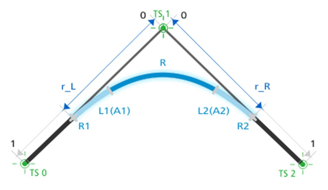
Ferrovia supports a number of linear and nonlinear transition curves: Clothoid and a range of cubic parabolas, including; cubic parabola, modified cubic parabola, Czech parabola and Romanian parabola Imbonatatita. Supported nonlinear parabolas include sinusoidal, Cosines, Bloss and S–curve parabola. Transition curves apply uniformly to horizontal transition curves and to cant gradients areas.
Turnouts
In turnout design you can take advantage of automatic turnout insertion, turnout parameter editing, and automatic turnout repositioning when alignment geometry changes apply. Included are various turnout types: straight-line turnouts (non-transformable), curve turnouts, symmetrical, and turnout crossings. Alongside predefined turnout geometry, a turnout catalogue provides users with the ability to edit or add custom geometry turnouts. Turnout reports provide the user with the tools to list turnout parameters and values in turnout tables, either in drawing or in external table files.


Rail Connections
Create rail connections interactively between parallel or non-parallel rail tracks in tangent or in curve with the geometry preview option. Having the advantage of using the same or different turnout types for rail connection gives users a wide range of geometry options to fit rail connections within constraint areas and limited design possibilities. Detailed design and editing of vertical connections in profile view add value to the comprehensive yet comfortable use of Ferrovia rail connection tools.


Detailed Cross Section Design and Editing
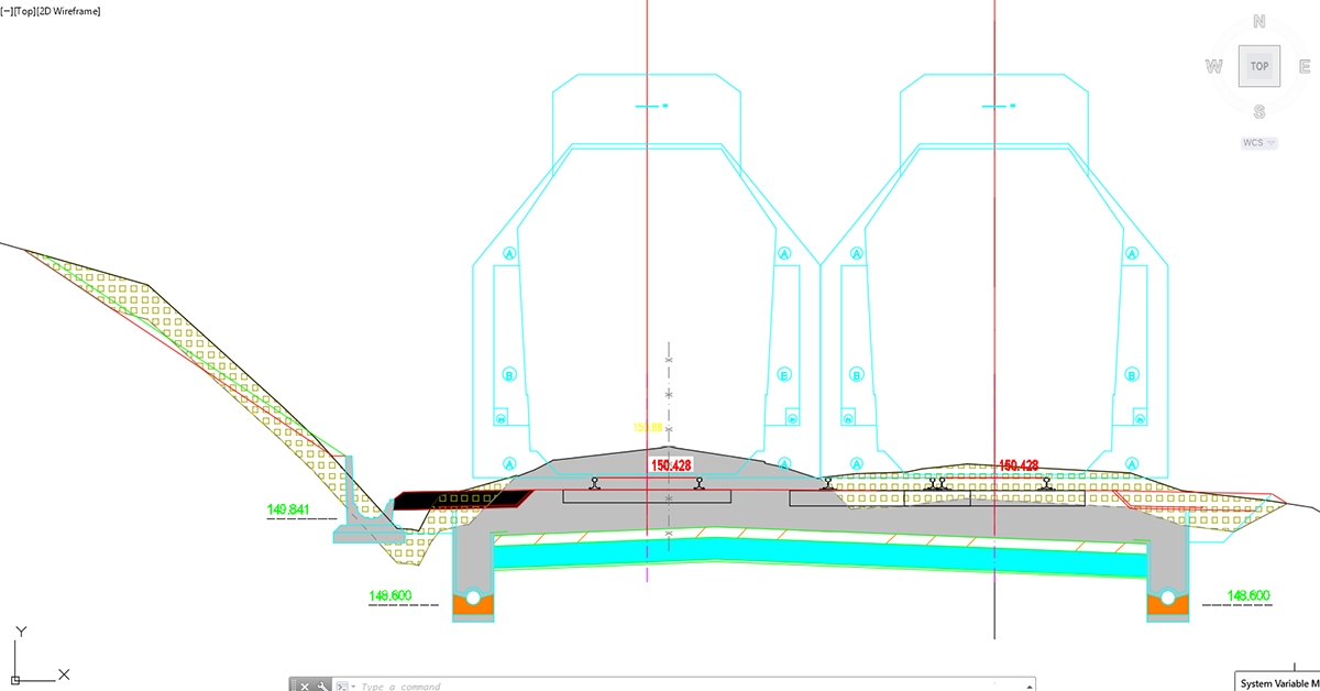
Ferrovia makes it possible to design and edit rail track cross sections in a detailed way with almost no geometry limitations to the final project design. Adding multiple rail tracks to a single cross section gives users control over the geometry between various rail tracks, rail tracks and roads or other infrastructure objects your project requires, and lets you define these areas with great accuracy and detail.


3D Surface and 3D Solid Model
Rail track 3D models can be created as a 3D surface or 3D solid model. 3D rail track surface models can be generated automatically from 3D rail-track cross-section geometry and terrain model, or it can be built with the grading function. The 3D solid model is created based on cross-section areas, where materials and volumes can be defined as extended data. With 3D solid tunnels, bridges and similar objects can be represented as well. Solid objects can be aligned with arcs and transition curves. All solid models, including extended data, can be imported into Autodesk Infraworks, Navisworks and then used in various BIM workflows.
Quantity take-off (QTO)
Ferrovia calculates material quantity take-off and features a QTO data export tool with custom defined Pay Item (Bill of Materials) options. It gives users the possibility to link material defined in the drawing with a material database in cost estimate software, thus supporting digital data transfer and fast cost recalculation when project changes arise.

Mass Haul Diagram
Mass haul diagram presents a graphical view of the material moved in the proposed design site. Mass haul diagrams help designers and contractors understand where gross material movements occur and compare the economies of alternative designs.
Road design tools
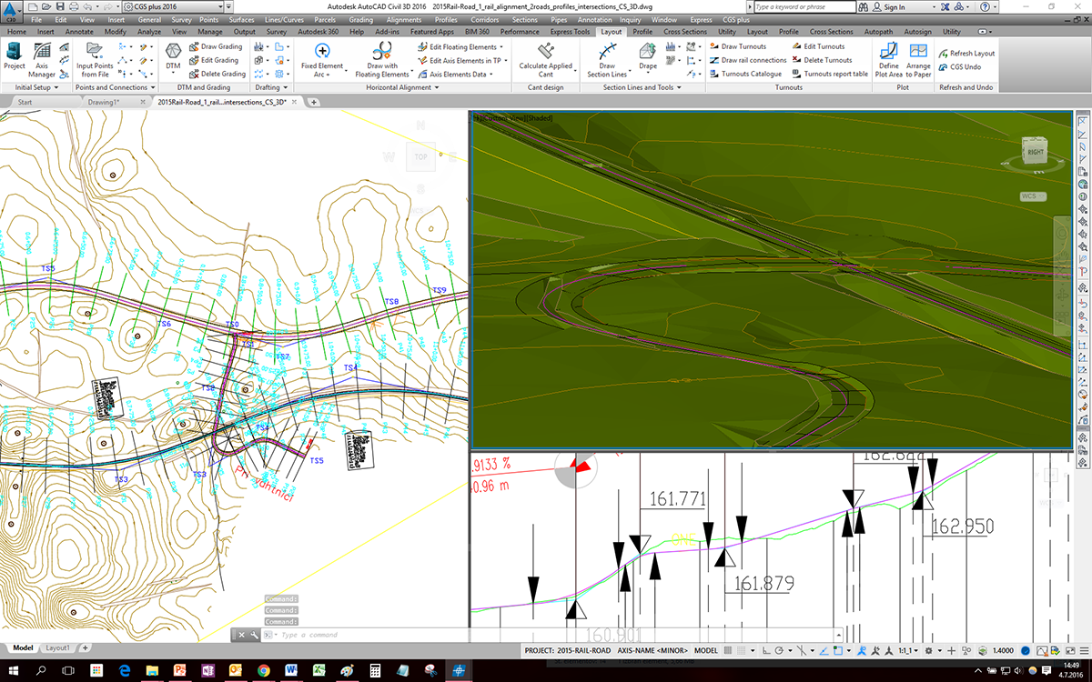
Road design tools are included in the Ferrovia Ultimate 4D software suite to provide users the tools they need to design roadways and rail tracks within the same project: Road–railway intersections for example, underpasses/overpasses, rail track construction access roads, side by side road/railway design, urban roads with tram lines, and more.
Horizontal and Vertical Regression Analysis
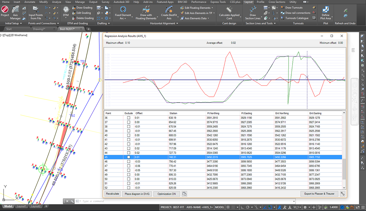
Ferrovia provides advanced and comprehensive technology for alignment and profile regression analysis and geometry optimizations options. Based on various input survey data and multiple editable parameters, alignments with appropriate transition curves are generated automatically, giving users the possibility to create realignment projects of any scale. Single regression elements are supported as well.
Options for converting surveyed rails to centerline review and edit regression points with point exclusion or inclusion in regression analysis lead to significant improvements in alignment or profile best-fit geometry. Multiple diagram options give users detailed information on curvature, transition areas, applied cant, and slew. All regression data is dynamically updated when changes occur.
Side-Track Objects Offset Analysis and Insurance Data Calculation
The side-track objects offset analysis tool give designers the tools to inspect any objects position alongside any alignment investigated in order to get offset data from side track masts, platform edges, retaining walls, tunnel contour, side track or road edges, etc.
For rail track realignment purposes insurance values can be calculated between fixed side objects (like overhead power line masts for example) and surveyed rail track position data in order to get absolute track layout data.
Google Maps & Google Street View
Google Maps Import makes it easy to import raster images and elevation data of a selected location from Google Maps into a DWG drawing in the selected coordinate system. Google Street View functionality is also available to allow the user to view the selected area interactively within the CAD environment.

Google Earth Export
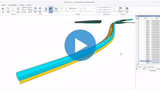
The Ferrovia BIM (3D solid) road infrastructure model can be quickly visualized directly into Google Earth. This allows us to present the project in an environment that enables the user to have exceptional visual performances.
Open Street Maps
Ferrovia provides geographic information for existing roads, railways and buildings for the planning area under consideration. Open Street Maps data is not locally restricted and can be used by the user for any area in the world where he plans projects.
Supported languages
- English
- Austrian German
- Czech
- German
- Hungarian
- Polish
- Serbian
- Slovenian
Supported CAD platforms
- Autodesk® AutoCAD® 2018 - 2025 (except AutoCAD LT)
- Autodesk® Civil 3D® 2018 - 2025
- BricsCAD® Pro, BIM and Ultimate V22 – V25
* Only 64-bit versions are supported
Select the version according to your needs
Available as a standalone or network license
- Survey data import
- Digital terrain modeling tool (CGS Labs DTM)
- 3D Grading
- Support for Civil 3D in BricsCAD surface
- Alignment design
- Profile design
- Cross sections design
- Turnouts design
- Linear and nonlinear transition curves
- 3D Railway modeling
- Points, lines and 3D solids projection to Profile View & Cross Sections Views
- Labeling and dimensioning tools
- Quantity Take-off & Mass Haul diagrams
- Interface for Civil 3D objects <-> Ferrovia
- Regression alignment and profile design (Best-Fit)
- Regression alignment and profile analysis and editing
- Rail Connections design
- Side-Track Objects Offset Analysis and Insurance Data Calculation
- Support for Plasser&Theurer tamping machinery
- Support for 3D solid objects
- Import of Google Maps geospatial data in CAD drawing
- Road design tools
- BIM object property tools (manager/editor/filter)
- 3D/BIM object clash analysis within AutoCAD, Civil 3D, and BricsCAD
- Import/Export LandXML data
- Import/Export 3D/BIM model to IFC 4.2 data format
- Export 3D railway model to Google Earth


Plateia, BIM software for road design and reconstruction

BIM Roadway Design
PLATEIA is a 3D road design and road reconstruction design software that supports BIM workflows and processes.
Intuitive user interface
Carefully designed UI and workflows are consistent with the road design engineering practice, which makes PLATEIA very easy-to-use.
For all design stages
PLATEIA's tools support the entire design process. From the input of survey data to the design of complex 3D road models and documentation.
Our Customers’ Journey


Key features of PLATEIA
Digital terrain modeling
The Surface creation tool is included in CGS Labs software to produce a detailed Digital Terrain Model (DTM) based on various surveys or other input data: total station data files, points, break lines, blocks, etc. This offers the possibility to use Plateia on plain AutoCAD or BricsCAD. Plateia supports also surfaces from Civil 3D and BricsCAD (V20 or newer).

Grading
Creation of complex slopes with multiple conditions in cut or fill gives users the capability to cover various design scenarios and geometry requirements for all kind of road projects, from simple forest road design to complex intersection geometry design. Furthermore, creating ponds, parking areas, platforms, road, rail tracks, river channels, and other features is easier and faster with CGS Labs grading functionality.
SITE DESIGN includes quick site modeling features, earthwork calculation, utility design, and productivity tools to speed up project delivery. It is ideal for fast conceptual projects, solution testing projects, detailed design, and earthwork projects including volume calculation, grading, and more. Serving data for machine control guidance, blueprints project delivery, survey data, and for great visualizations.
Surface
The terrain design is the main benefit of the new collection. Surface can be created based on the survey data or simply imported from Google Maps. The biggest advantage of this surface tool is that it creates ultralight surface models in an instant.
Google Maps & Google Street View
Google Maps Import makes it easy to import raster images and elevation data of a selected location from Google Maps into a DWG drawing in the selected coordinate system. Google Street View functionality is also available to allow the user to view the selected area interactively within the CAD environment.
Google Earth Export
Plateia BIM (3D solid) road infrastructure model can be quickly visualized directly into Google Earth. This allows us to present the project in an environment that enables the user to have exceptional visual performances.
Powerful geometry design tools
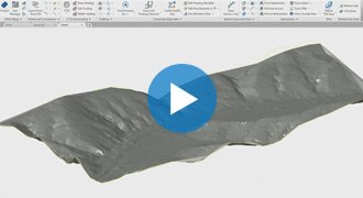
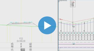
Plateia provides a wide range of advanced alignment, profile geometry design, and editing tools. They include P(V)I design, floating and fixed elements design and alignment design created from the existing entities.
Ultimately creating a best-fit alignment based on existing road centerline or road edge survey data. Superelevation calculation features a comprehensive definition and editing tool.
Plateia supports several superelevations definitions and pivot point options according to various European and AASHTO roadway design standards. A number of alignment labels according to different country standards, reports, and data export options offer the flexibility to cover a wide range of user requirements.
Intersections and roundabouts
Automated intersection and roundabout design based on road geometry defined by alignment, profile and super-elevations.
The 3D Intersections function automatically adjusts secondary road profile and super elevation parameters with corresponding user defined curb returns.
Automated intersection design results in detailed 3D intersection geometry for X or T shaped intersection types. Use the grading/surface mode with various parameters to customize 3D intersection geometry.


3D surface and 3D solid model
Roadway 3D models in Plateia are generated as 3D surfaces or 3D solid models. 3D roadway surface model is built automatically from 3D road edges and terrain model, or it can be built with the grading function. 3D solid model is created based on cross-section areas, where materials and volumes can be defined as extended data.
With 3D solids, we can also build tunnels, bridges and similar objects. Solid objects can be aligned with arcs and transition curves. All solid models, including extended data, can be imported into Autodesk Infraworks, Navisworks and can be used in various BIM workflows.
Detailed cross section design and editing
Plateia provides capabilities for designing and editing roadway cross sections in a detailed way with almost no geometry limitations to the final project design. Adding multiple roadways to a single cross section gives you control over the geometry between the roads and other infrastructure objects your project requires, and lets you define these areas with great accuracy and detail.


Quantity take-off (QTO)
Plateia calculates material quantity take-off and features a QTO data export tool with custom defined Pay Item (Bill of materials) options. It gives users the possibility to link material defined in the drawing with a material database in cost estimate software, thus supporting digital data transfer and fast cost recalculation when project changes arise.

Visibility and stop sight distance
The Visibility and Stop sight distance road geometry tool provides graphical visibility distance analysis required to safely stop a vehicle traveling at design speed. This facilitates planning to avoid collisions with any other immobile objects obstructing the driving path.
The road reconstruction / rehabilitation function offers powerful regression analysis tools for best-fit alignment and profile creation based on existing road centerline or road edge surveyed data.
Existing road superelevation comparison with new superelevation calculation and editing enhancements provide designers the needed tools to tackle demanding geometrical restrictions.
Integrated road reconstruction & rehabilitation tools for calculation of material removal and / or resurfacing material quantities result in new 3D road geometry data linked with QTO information.
| AUSTRIA | Österreichischen Richtlinien für Linienführung von Straßen RVS 3.23. |
| BOSNIA and HERZEGOVINA | Smjernice za projektovaje, građenje, održavanje i nadzor na putevima, 2005. |
| CROATIA | Pravilnik o osnovnim uvjetima kojima javne ceste izvan naselja i njihovi elementi moraju udovoljavati sa stajališta sigurnosti prometa (NN br. 110/01) |
| CZECH REPUBLIC | Projektování silnic a dálnic, ČSN 73 6101 |
| GERMANY | Richtlinien für die Anlage von Landstraßen, RAL 2012, RAA-2008, RASt-06 |
| POLAND | Warunków technicznych, jakim powinny odpowiadać drogi publiczne i ich usytuowanie, DU 43/1999 Rizp. 430 |
| SERBIA | Pravilnik o uslovima koje sa aspekta bezbednosti saobraćaja moraju da ispunjavaju putni oobjekti i drugi elementi javnog puta, Službeni glasnik RS, br 50/2011; JUS (UL SFRJ 35/939, 26.06.1981 |
| SLOVENIA | Pravilnik o projektiranju cest, UL RS 91/9303, 14.10.2005 |
| HUNGARY | Partially implemented. |
| For information about other country-specific standards please contact us! | |
Autosign is a professional software solution for planning traffic signal design in CAD environments. It generates detailed layouts and reports. Autosign includes extensive collections of country-specific traffic sign libraries and road markings.
*Autosign is available in Plateia Ultimate and Professional version.

Autopath is a professional software for swept path analysis and vehicle turning simulations. With it, you can easily and quickly simulate vehicle maneuvers and check transportability of all types of road design projects: on roads, intersections, roundabouts, hairpin turns, underpasses, overpasses … [read more about Autopath]
*Autopath is available in Plateia Ultimate version.

CGS Labs solutions provide extensive BIM data support not limited to CAD platforms in use. 3D roadway, railway or river channel models are generated as detailed 3D solid objects with extended BIM metadata attached to objects, or as multiple surfaces for use with computer guided machines etc.
Plateia offers capable Property Manager for adding and changing 3D solids property data, which enables COBie (Construction Operations Building Information Exchange) compatibility.
Plateia 3D models and attribute data can be exported to IFC files. IFC export format is regularly updated according to buildingSMART International specifications.
Clash detection tool enables designer to search for possible collisions among selected 3D solid objects within the drawing itself thus saving the time to export models and create clash analysis in third party applications outside CAD environment.
Watch webinars for PLATEIA software


Supported languages
- Austrian German
- Croatian
- Czech
- English (International)
- English (USA-AASHTO)
- German
- Hungarian
- Polish
- Serbian
- Slovenian
Supported CAD platforms
- Autodesk® AutoCAD® 2018 - 2025 (except AutoCAD LT)
- Autodesk® Civil 3D® 2018 - 2025
- BricsCAD® Pro, BIM and Ultimate V22 – V25
* Only 64-bit versions are supported
Select the version according to your needs
Available as a standalone or network license
- Survey data import
- Digital terrain modeling tool (CGS Labs DTM)
- 3D Grading
- Support for Civil 3D and BricsCAD surface
- Alignment design
- Profile design
- Cross-sections design
- Road super elevations
- 3D Road modeling
- Points, lines and 3D solids projection to Profile View & Cross Sections Views
- Labeling and dimensioning tools
- Visibility analysis & Stop sight distance
- Quantity Take-off & Mass Haul diagrams
- Intersections design 2D/3D
- Roundabout design
- Intersections islands design
- Curb return fillets
- Interface for Civil 3D objects <-> Plateia
- Regression alignment and profile design (Best-Fit)
- Regression alignment and profile analysis and editing
- Side road objects distance calculation (Off-Set calculation)
- Import of Google Maps geospatial data in CAD drawing
- 2D Traffic signs and road markings design (Autosign Professional)
- 3D/BIM Traffic signs and road markings design & visualization (Autosign Ultimate)
- 2D/3D Vehicle swept path analysis and turning simulation (Autopath Ultimate)
- Support for 3D Solid objects
- BIM object property tools (manager/editor/filter)
- 3D/BIM object clash analysis within AutoCAD, Civil 3D, and BricsCAD
- Import/Export LandXML data
- Import/Export 3D/BIM model to IFC 4.2 data format
- Export 3D road model to Google Earth